Advanced programmable closed loop fan control method

a fan control and programmable technology, applied in the field of advanced programmable closed loop fan control methods, can solve the problems of increasing system power consumption, general ineffective minimizing power consumption, dynamic nonlinearity, etc., and achieve the effect of reducing system power consumption and the audible noise of the fan

a fan control and programmable technology, applied in the field of advanced programmable closed loop fan control methods, can solve the problems of increasing system power consumption, general ineffective minimizing power consumption, dynamic nonlinearity, etc., and achieve the effect of reducing system power consumption and the audible noise of the fan

US20060181232A1Active Publication Date: 2006-08-17TEXAS INSTR INC

Image

  • Advanced programmable closed loop fan control method
  • Advanced programmable closed loop fan control method
  • Advanced programmable closed loop fan control method

Examples


Embodiment Construction

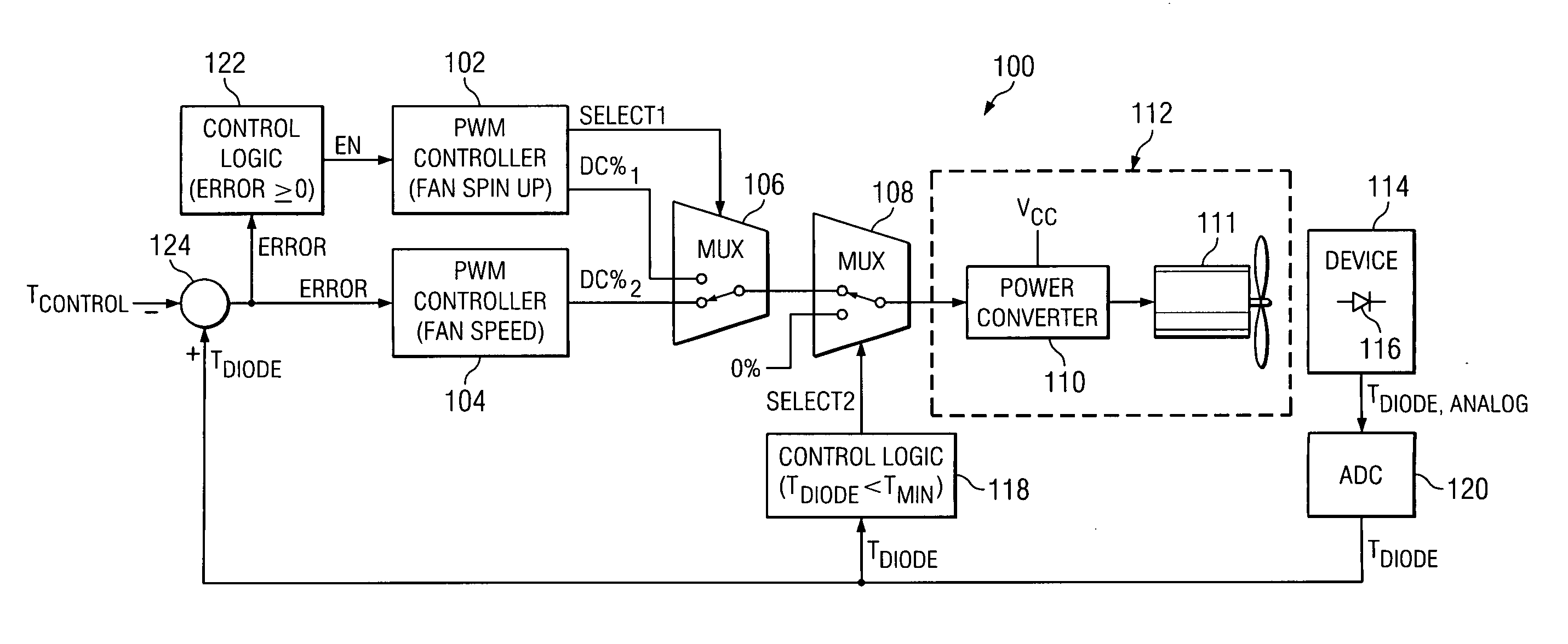
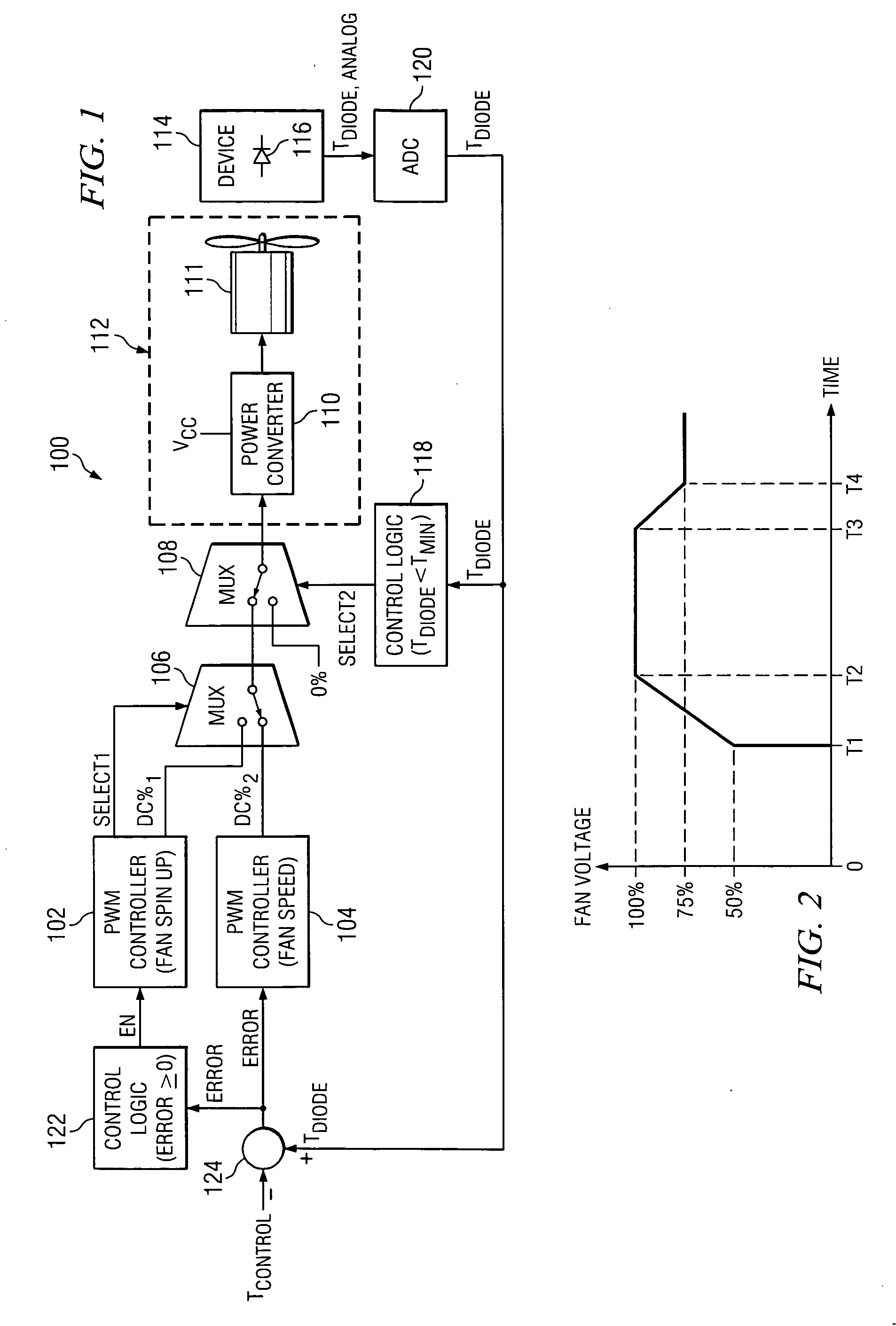
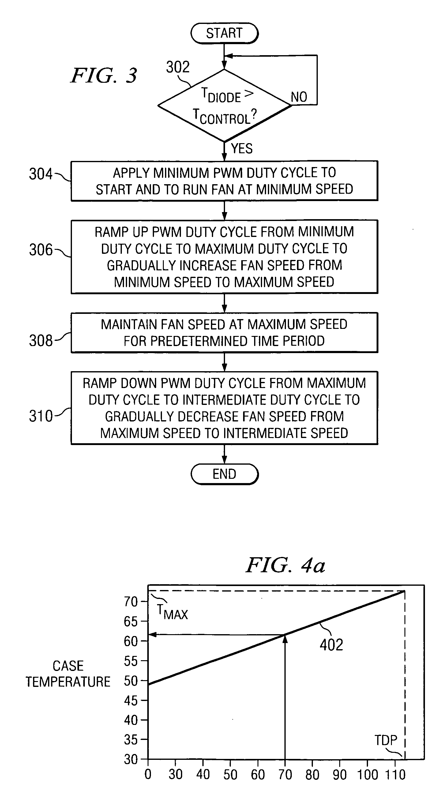
[0025] A fan control system and method is disclosed that provides controllable acceleration and deceleration of a fan during an initial fan spin up, and then runs the fan at speeds sufficient to maintain the operating temperature of a computer or electronic device or component at approximately a predetermined control level, thereby minimizing the power consumption of the system and the audible noise of the fan. The fan control system provides programmable closed loop control of the speed and acceleration of the fan based on the sensed temperature of the device or component.

[0026]FIG. 1 depicts an illustrative embodiment of a fan control system 100, in accordance with the present invention. In the illustrated embodiment, the fan control system 100 comprises a first fan controller 102, a second fan controller 104, control logic 118 and 122, a pair of multiplexors (MUXs) 106 and 108, a fan / motor assembly 112 including a power converter 110 and a motor and fan 111, a temperature sensor...


PUM


Abstract

A fan control system and method that maintains the operating temperature of computer and electronic devices or components at about a predetermined control level to minimize power consumption and audible noise. The fan control system is a programmable closed loop system including a temperature sensor, first and second fan controllers, and a fan / motor assembly including a power converter, a motor, and a fan. The first fan controller provides programmable acceleration / deceleration of the fan during an initial fan spin up, and the second fan controller runs the fan only as fast as necessary to keep the sensed temperature level of a computer device as close as possible to the predetermined control level, thereby minimizing the power consumption of the system and the audible noise of the fan.

Description

CROSS REFERENCE TO RELATED APPLICATIONS [0001] N / A STATEMENT REGARDING FEDERALLY SPONSORED RESEARCH OR DEVELOPMENT [0002] N / A BACKGROUND OF THE INVENTION [0003] The present invention relates generally to systems and methods of controlling a fan to cool computer and electronic devices, components, and / or equipment enclosures, and more specifically to a system and method of controlling a cooling fan based on the sensed die temperature of a CPU. The presently disclosed system and method provide for reduced system power consumption and reduced audible fan noise. [0004] In recent years, operating speeds of computer devices such as central processing units (CPUs) and microprocessors have undergone dramatic increases. Because increases in computer device speeds are typically accompanied by significant increases in the level of current flowing through the devices, the amount of heat dissipated by such computer devices has also risen dramatically. For this reason, there is a need for improve...

Claims


Application Information

Patent Timeline
17 Aug 2006
Publication
US20060181232A1
IPC
H02P7/00
CPC
G06F1/206; G06F1/3203; H02P23/0063; Y02B60/1275; H02P29/60; Y02D10/00
Inventors
OLJACA, MIROSLAV; JOHNSON, JEFFREY DAVID