Radio transceiver having a phase-locked loop circuit

a technology of phase-locked loop circuit and radio transceiver, which is applied in the direction of electrical equipment, pulse automatic control, etc., to achieve the effects of convenient maintenance, convenient use, and reduced manufacturing cos

Inactive Publication Date: 2006-08-17
NOKIA CORP
View PDF13 Cites 7 Cited by
  • Summary
  • Abstract
  • Description
  • Claims
  • Application Information

AI Technical Summary

Benefits of technology

[0015] A further object of the present invention is to increase the capacity of the manufacturing process by simplifying the alignment process leading to shorter cycle times, and to simplify the construction of a wide frequency range PLL.
[0027] Preferably the control unit comprises a time delay unit, to prevent the unit from continuously switching from one VCO to another. This is preferably assured by an adequate overlap of the frequency ranges of the VCOs, or a hysteresis characteristic in the control unit. It prevents the control unit from continuously switching from one VCO to another even if the overlap of adjoining frequency ranges is too small, due to operation conditions or production tolerances.
[0028] According to another preferred aspect of the invention a transmitter, a receiver or a transceiver using a PLL according to the invention are easier to use, less susceptible to interference and less power consuming, especially in mobile electrical appliances.
[0032] Preferably the signals from the branch-off line to the filtering device are logic- or time-processed. With this processing, measurement of noise signals can be avoided. The use of logic gates allows use of only one low-pass filter even if two ore more charge pumping means are used.
[0036] According to the present invention, a wide frequency range transceiver is provided using a phase locked loop circuit (PLL) that can automatically switch between a multitude of voltage controlled oscillators (VCO) and presents a number of advantages to the manufacturer as well as for the user or a maintenance technician. The manufacturer can save nearly the whole alignment process during the assembly, as well as means for storage of the switch point of the selective switching means. The user benefits from the fact that the PLL of the transceiver according to the invention is always in a linear operation state, irrespective of external conditions as temperature or other frequency range shifting effects. The user of the transceiver may ignore any variable resistor positions inside the transceiver. A maintenance technician benefits from the fact, that in the invention there are no variable resistors susceptible to dust and humidity, no storage means whose data may get lost, and no difficulty to measure analog signals in order to find a failure or defect on the circuit board.
[0039] A transceiver using a PLL according to the invention is cheaper and easier to manufacture, easier to use and easier to maintain.

Problems solved by technology

In the overlapping region of the frequency ranges the problem resides in determining which of both VCOs should be used to generate a given frequency.
The main disadvantage of this known technique is the fact that the frequency range of each VCO has to be measured, the switching points have to be determined, and all these data have to be stored in a special storing means in the transceiver.

Method used


Image

  • Radio transceiver having a phase-locked loop circuit
  • Radio transceiver having a phase-locked loop circuit
  • Radio transceiver having a phase-locked loop circuit

Examples


Embodiment Construction

[0045] While the following description is in the context of wireless communication systems involving portable or mobile radio telephones and / or computer communication systems, it will be understood by those skilled in the art that that the present invention may be applied to other oscillating devices. Moreover, the present invention may be used in any non radio frequency emitting device as a variable oscillator such as computers etc.

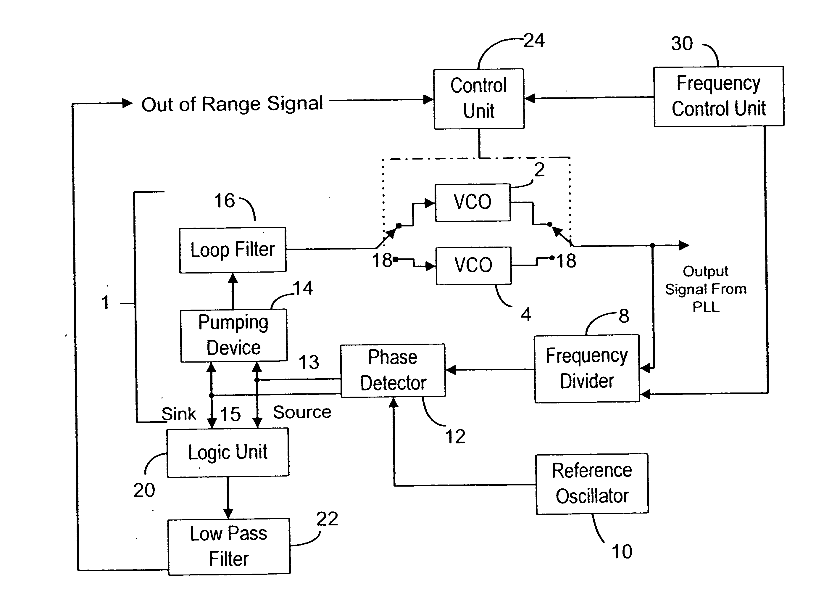
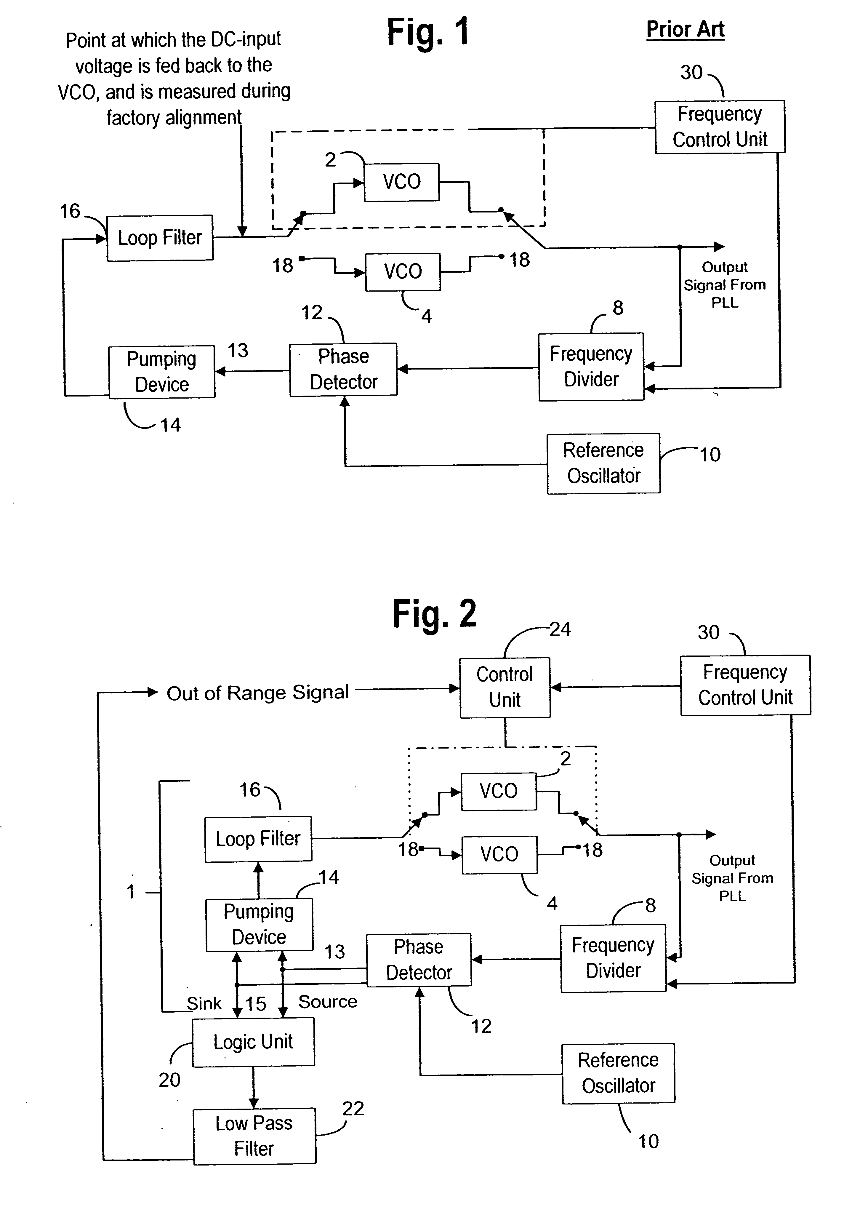
[0046]FIG. 1 describes a conventional solution of a two VCO PLL factory alignment. A conventional wide frequency range two VCO PLL comprises two VCOs 2,4, to generate a variable frequency related to an input DC voltage. It also comprises a frequency divider 8 to divide the frequency of said VCO, a reference oscillator 10 and a phase detector 12 to compare the phases of the divided frequency and of the reference oscillator. The phase detector connected to the pumping means 14, generates a DC voltage signal related to the divergence of the divided frequen...


PUM


Abstract

The invention relates to a phase-locked loop circuit (1) in a radio transceiver for the detection of the linear operation of a first voltage controlled oscillator (2), which comprises a frequency divider (8), a reference oscillator (10), a phase detector (12) to compare the phases of the reference oscillator (10) with a divided frequency of the frequency divider (8), and a charge pumping means (14) connected to the phase detector (12) and is characterised in that the connection (13) between the phase detector (12) and the charge pumping means (14) has at least one branch-off line (15) connected to at least one filtering means (22), whose output voltage is related to the linear operation of the voltage controlled oscillator (2).

Description

CROSS REFERENCE TO RELATED APPLICATION [0001] This application is a continuation of U.S. patent application Ser. No. 10 / 433,745 filed on Nov. 4, 2003, which application was filed as an entry into the U.S. national phase under §371 for International Application No. PCT / EP01 / 13238 having an international filing date of Nov. 15, 2001, and which in turn claims priority to European Patent Application 00126868.9, filed on Dec. 7, 2000.TECHNICAL FIELD [0002] The present invention relates generally to radio transceivers using a voltage controlled oscillator (VCO) in a phase-locked loop circuit (PLL). It also relates generally to radio transceivers optimised to achieve a wide range frequency coverage using the ability to select among a number of VCOs in order to find the best suited VCO to generate a predetermined channel frequency. In particular the present invention relates to a phase locked loop circuit for the detection of the linear operation of the VCO and a method for its operation. B...

Claims


Application Information

Patent Timeline
Patent Type & Authority Applications(United States)
IPC IPC(8): H03L7/06H03L7/089H03L7/099H03L7/10H03L7/18
CPCH03L7/0891H03L7/099H03L7/10H03L7/18
Inventor BURGESS, PAUL
Owner NOKIA CORP
Why Eureka
Try Eureka