
System and method for combining displaced phase center antenna and space-time adaptive processing techniques to enhance clutter suppression in radar on moving platforms

a technology of space-time adaptive processing and displaced phase center antenna, which is applied in the field of radar systems, can solve the problems of significant technical problems, affecting the detection of valid, so as to enhance the suppression of clutter and target detection, improve system performance, and process clutter in a more benign environment

Inactive Publication Date: 2006-08-17
HONEYWELL INT INC
View PDF8 Cites 25 Cited by
  • Summary
  • Abstract
  • Description
  • Claims
  • Application Information

AI Technical Summary

Benefits of technology

The present invention is a system and method for improving the suppression of clutter and target detection in a radar system located on a moving platform. By using a DPCA processing unit to remove most of the rapidly varying clutter and a STAP processing unit to fine-tune the clutter suppression process, the system performance is improved. Additionally, using a DPCA processing unit provides independence from clutter statistics and using a STAP processing unit provides fine tuning of the suppression process. This invention is particularly useful for space-based radar platforms, which are relatively stable and not subject to air turbulence or wave motion.

Problems solved by technology

As such, clutter is a form of radar interference that hinders the identification of valid, moving targets.
However, with moving radar platforms (e.g., ship-based radar, airborne radar, space-based radar), the suppression of clutter is a relatively difficult problem, because the clutter also appears to be moving due to the movement of the radar platform.
Consequently, the detection of valid, moving targets within a moving clutter environment is a significant technical problem that exists.

Method used


Image

  • System and method for combining displaced phase center antenna and space-time adaptive processing techniques to enhance clutter suppression in radar on moving platforms
  • System and method for combining displaced phase center antenna and space-time adaptive processing techniques to enhance clutter suppression in radar on moving platforms
  • System and method for combining displaced phase center antenna and space-time adaptive processing techniques to enhance clutter suppression in radar on moving platforms

Examples


Embodiment Construction

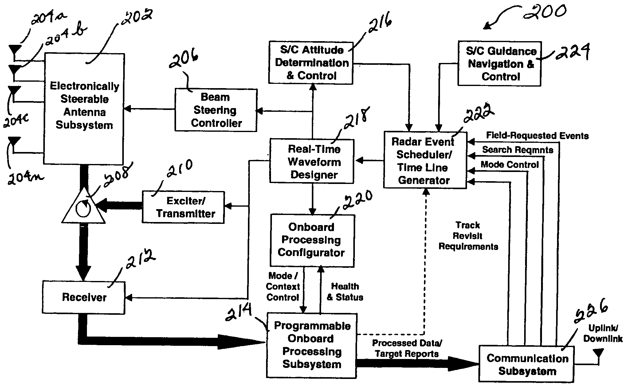
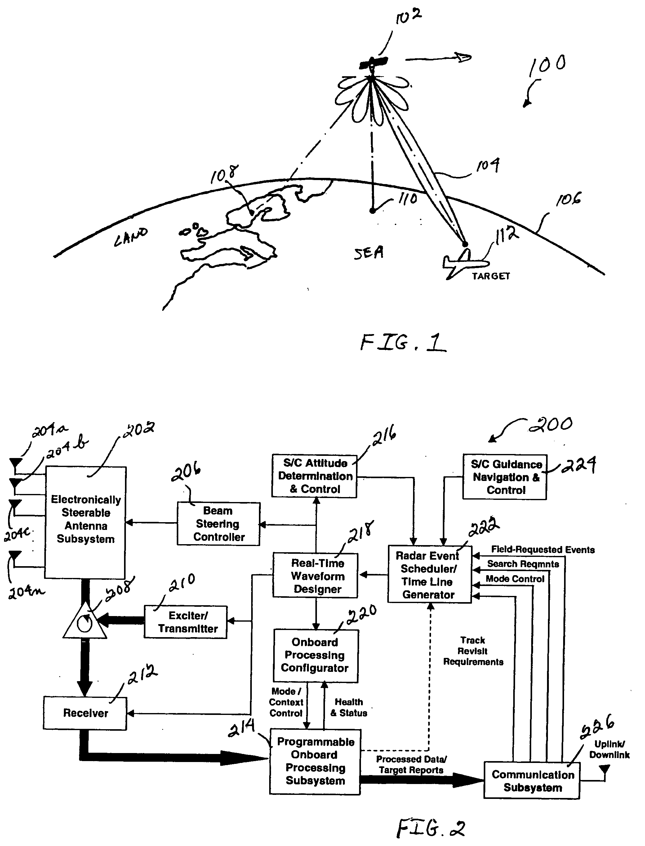
[0017] Referring now to the figures, FIG. 1 depicts a pictorial representation of an example of a space-based radar system environment 100, which can be used to illustrate a preferred embodiment of the present invention. For this exemplary embodiment, an MTI radar system 102 is located on a satellite platform that is in orbit over a portion of the Earth 106. The satellite platform for radar system 102 can be in a Highly Elliptical Orbit (HEO), a Medium Earth Orbit (MEO), or a Low Earth Orbit (LEO). Also, radar system 102 can be located on a space-based vehicle or station, such as, for example, a space shuttle or similar space vehicle, space-based laboratory, space station, etc. As such, radar system 102 can be located on any appropriate space-based platform. In any event, although a space-based radar system is described with respect to this embodiment, the present invention is not intended to be so limited, and can include radar systems located on other moving platforms as well, suc...


PUM


Abstract

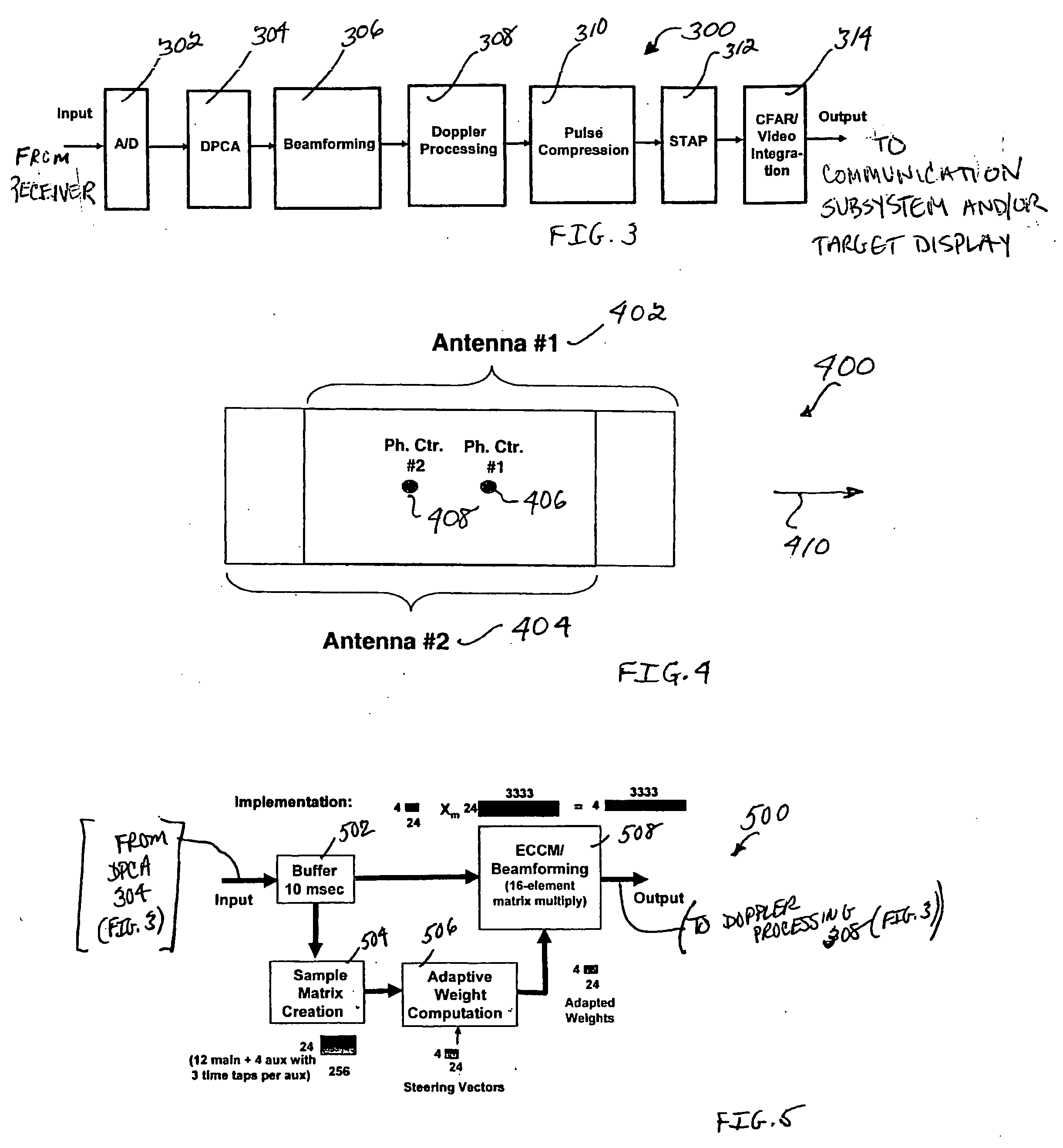
A system and method are disclosed for enhancing the suppression of clutter and target detection in a radar system located on a moving platform. For example, a radar system including an MTI subsystem is located on a moving platform (e.g., ship-borne, airborne or space-based radar system) with a DPCA processing unit located nearer to the front end of the radar receiver, and a STAP processing unit located nearer to the back end. The DPCA processing unit provides gross cancellation and suppression of the received clutter signals, and the STAP processing unit provides fine tuning for the clutter suppression process. In other words, the front end DPCA processing unit removes most of the rapidly varying clutter, which gives the back end STAP processing unit a more benign clutter environment to process. As such, using a DPCA processing unit on a space-based radar platform improves system performance, because the space-based platform is relatively stable and not subject to air turbulence or wave motion. Also, using a DPCA processing unit provides independence from clutter statistics, which is important because relatively little empirical clutter data is available from space-based radar platforms. Using a STAP processing unit for clutter suppression on the space-based radar platform provides fine tuning of the suppression process.

Description

BACKGROUND OF THE INVENTION [0001] 1. Technical Field [0002] The present invention relates generally to the field of radar systems, and more particularly, but not exclusively, to a system and method for combining Displaced Phase Center Antenna (DPCA) and Space-Time Adaptive Processing (STAP) techniques in order to enhance clutter suppression and target detection in radar systems located on moving platforms. [0003] 2. Description of Related Art [0004] Moving Target Indication (MTI) radar systems are used to reject signals received from fixed objects (“clutter”), and enhance the detection of signals received from valid, moving targets. Typically, coherent MTI systems use the Doppler shift effect of moving targets to distinguish them from the fixed objects or clutter. Essentially, clutter is a collective term referring to those objects that are not valid targets and cause unwanted radar reflections to mix with target reflections. Examples of clutter are non-moving objects on land surfa...

Claims


Application Information

Patent Timeline
Patent Type & Authority Applications(United States)
IPC IPC(8): G01S13/52
CPCG01S7/2813G01S13/449G01S13/5242G01S13/5244
Inventor SAMSON, JOHN R. JR.
Owner HONEYWELL INT INC
Learn More