System and method for signal processing for a workpiece surface inspection system

a workpiece surface and signal processing technology, applied in the direction of error detection/correction, image enhancement, instruments, etc., can solve the problems of increasing the difficulty and expense of their maintenance and repair, and the amplitude and direction of scattered light from the scratch, so as to achieve high sensitivity and reliability

Active Publication Date: 2006-08-17
ADE CORPORATION
View PDF14 Cites 145 Cited by
  • Summary
  • Abstract
  • Description
  • Claims
  • Application Information

AI Technical Summary

Benefits of technology

[0008] Accordingly, an object of the present invention according to one aspect is to provide apparatus and met

Problems solved by technology

This often causes changes in the amplitude and direction of scattered light from the scratch as the wafer rotates.
This highly controlled

Method used


Image

  • System and method for signal processing for a workpiece surface inspection system
  • System and method for signal processing for a workpiece surface inspection system
  • System and method for signal processing for a workpiece surface inspection system

Examples


Embodiment Construction

[0143] Reference will now be made in detail to the presently preferred embodiments and methods of the invention as illustrated in the accompanying drawings, in which like reference characters designate like or corresponding parts throughout the drawings. It should be noted, however, that the invention in its broader aspects is not limited to the specific details, representative devices and methods, and illustrative examples shown and described in this section in connection with the preferred embodiments and methods. The invention according to its various aspects is particularly pointed out and distinctly claimed in the attached claims read in view of this specification, and appropriate equivalents.

Surface Inspection System

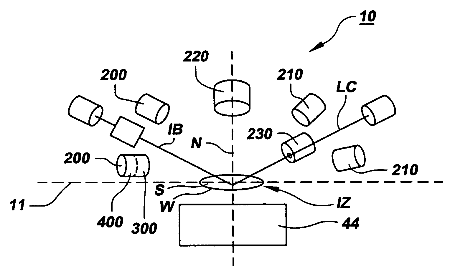
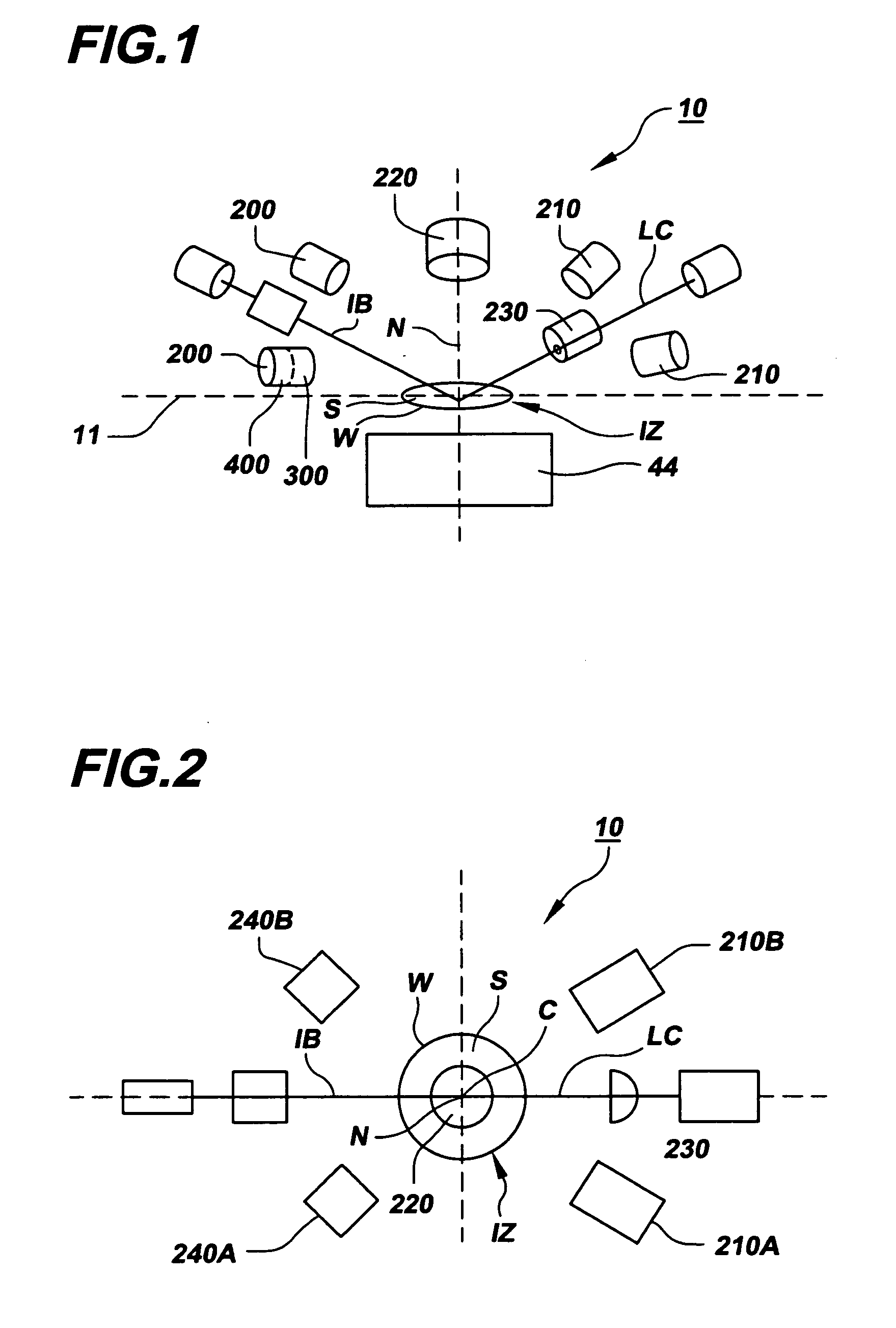
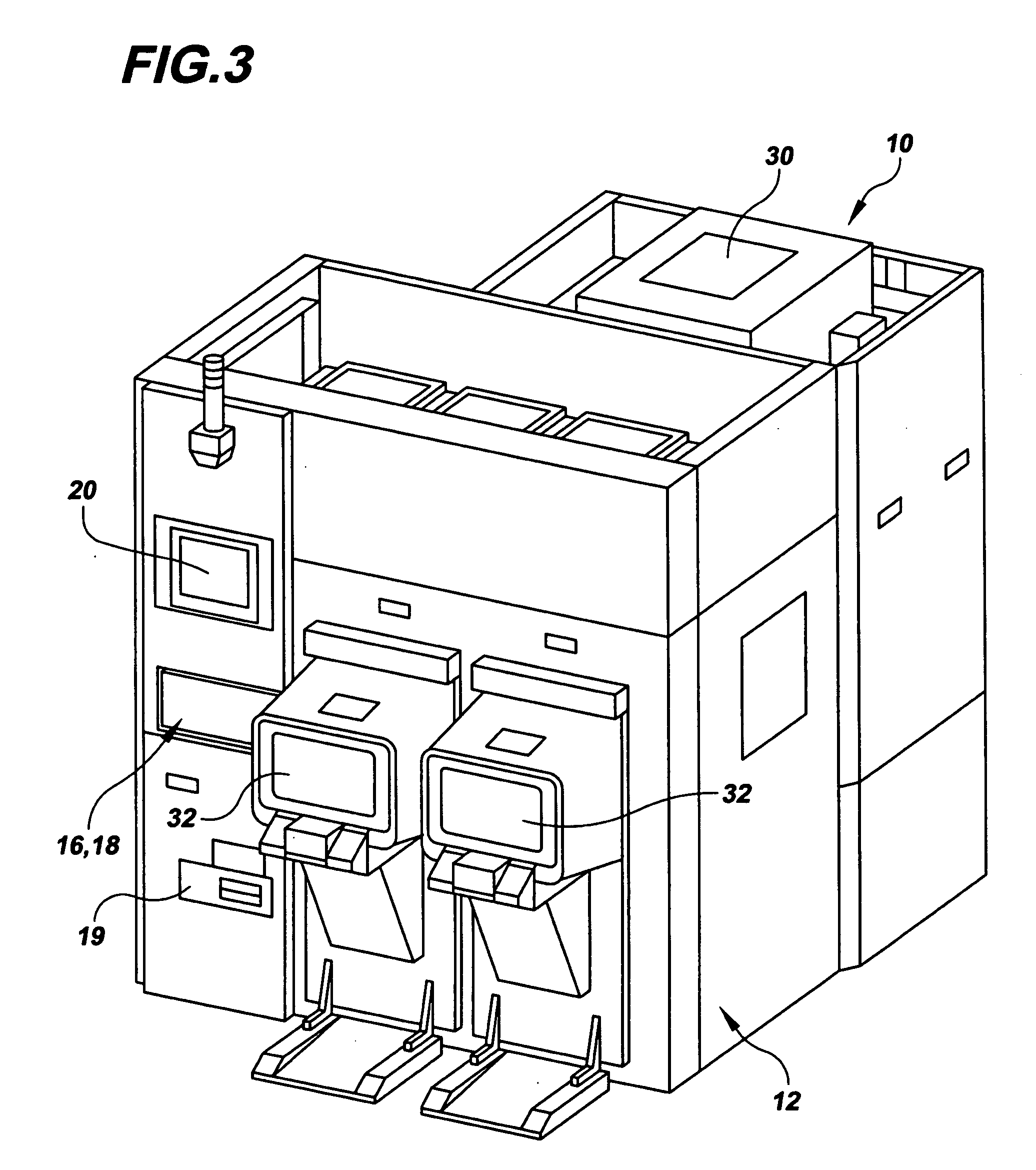
[0144] A surface inspection system 10 and related components, modules and subassemblies in accordance with various aspects of the invention will now be described. Surface inspection system 10 is designed to inspect a surface S or surfaces of a workpiece W, such ...


PUM

PropertyMeasurementUnit
Sizeaaaaaaaaaa
Electric potential / voltageaaaaaaaaaa
Areaaaaaaaaaaa

Abstract

A surface inspection system, as well as related components and methods, are provided. The surface inspection system includes a beam source subsystem, a beam scanning subsystem, a workpiece movement subsystem, an optical collection and detection subsystem, and a processing subsystem. The signal processing subsystem comprises a series of data acquisition nodes, each dedicated to a collection detection module and a plurality of data reduction nodes, made available on a peer to peer basis to each data acquisition nodes. Improved methods for detecting signal in the presence of noise are also provided.

Description

CROSS-REFERENCE TO RELATED APPLICATION [0001] The present application claims the benefit of the filing date of U.S. Provisional Patent Application No. 60 / 638,529, filed Dec. 19, 2004, currently pending, the entire disclosure of which is incorporated herein by reference.BACKGROUND OF THE INVENTION STATEMENT REGARDING FEDERALLY SPONSORED RESEARCH OR DEVELOPMENT [0002] N / A FIELD OF THE INVENTION [0003] The present invention relates to technology for the inspection of a surface or surfaces of a workpiece, such as a semiconductor wafer, chip, or the like. More particularly, it relates to apparatus and methods for inspection of such workpiece surfaces using electromagnetic energy, e.g., light, to scan the surface to obtain characteristics of the surface or other information concerning the surface. DESCRIPTION OF THE RELATED ART [0004] There are a number of applications in which it is desirable or advantageous to inspect a surface or surfaces of a workpiece to obtain information about the ...

Claims


Application Information

Patent Timeline
IPC IPC(8): G01N21/00
CPCG01N21/21G01N2201/105G01N21/4738G01N21/474G01N21/55G01N21/88G01N21/8806G01N21/9501G01N21/956G01N2021/4707G01N2021/4711G01N2021/4792G01N2021/556G01N2021/8864G01N2021/8877G01N2021/8896G06T7/0004G06T2207/30148G01N21/95Y10T29/49826G01N2021/8848G01N2201/0612G01N21/47G01N2021/8809
Inventor ANDREWS, SCOTTJUDELL, NEILRICHARD EARL, BILLSTIEMEYER, TIMOTHY R.
Owner ADE CORPORATION
Why Eureka
Try Eureka