Method and apparatus for suppression of crosstalk and noise in time-division multiplexed interferometric sensor systems

a time-division multiplexed interferometric and sensor technology, applied in the field of interrogating interferometric sensors, to achieve the effect of suppressing interference signals and reducing crosstalk and nois

Active Publication Date: 2006-08-17
OPTOPLAN
View PDF17 Cites 23 Cited by
  • Summary
  • Abstract
  • Description
  • Claims
  • Application Information

AI Technical Summary

Benefits of technology

[0014] Embodiments of the invention generally relate to reducing crosstalk and noise in time-division multiplexed (TDM) systems by suppressing interference signals from unwanted light components that have propagated noise contributing pathways through the sensor network. The unwanted light components may lead to crosstalk and noise if they overlap in time with an optical signal received from an interrogated sensor. Noise and crosstalk are contributed from interference at the receiver unit between optical signals received from the interrogated sensor and unwanted light pulses that have propagated noise contributing pathways. Other contributions may come from interference between signals received from the interrogated sensor and leakage light that has propagated pathways of other time-division multiplexed sensors or other pathways with moderate transmission loss. Noise and crosstalk due to the unwanted interference between the optical signal from the sensor and unwanted light components can be suppressed by modulating the optical phase in the transmission time slots in such a way that the unwanted interference signals are distributed to frequency bands that do not affect the demodulated sensor signal.

Problems solved by technology

The unwanted light components may lead to crosstalk and noise if they overlap in time with an optical signal received from an interrogated sensor.

Method used


Image

  • Method and apparatus for suppression of crosstalk and noise in time-division multiplexed interferometric sensor systems
  • Method and apparatus for suppression of crosstalk and noise in time-division multiplexed interferometric sensor systems
  • Method and apparatus for suppression of crosstalk and noise in time-division multiplexed interferometric sensor systems

Examples


Embodiment Construction

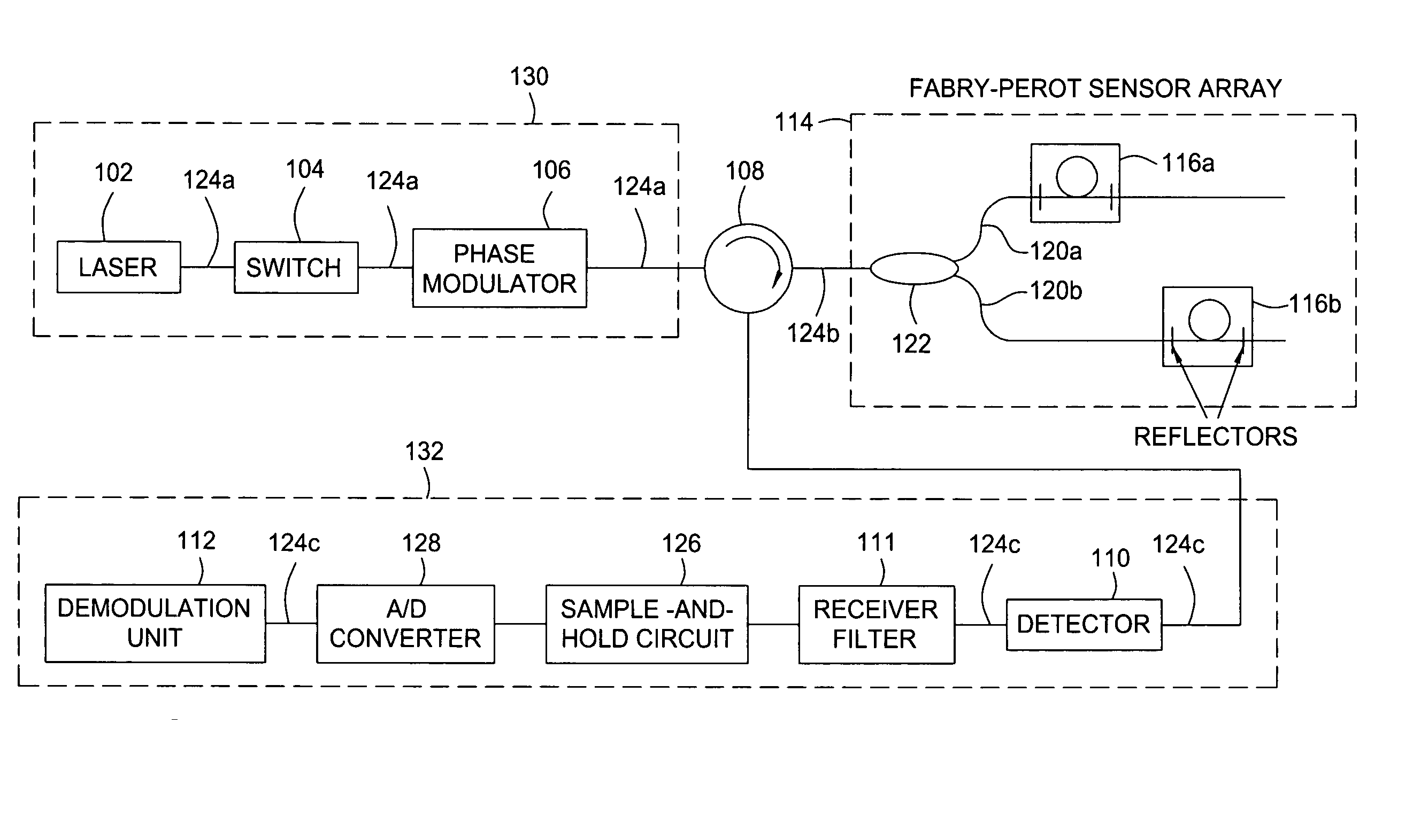
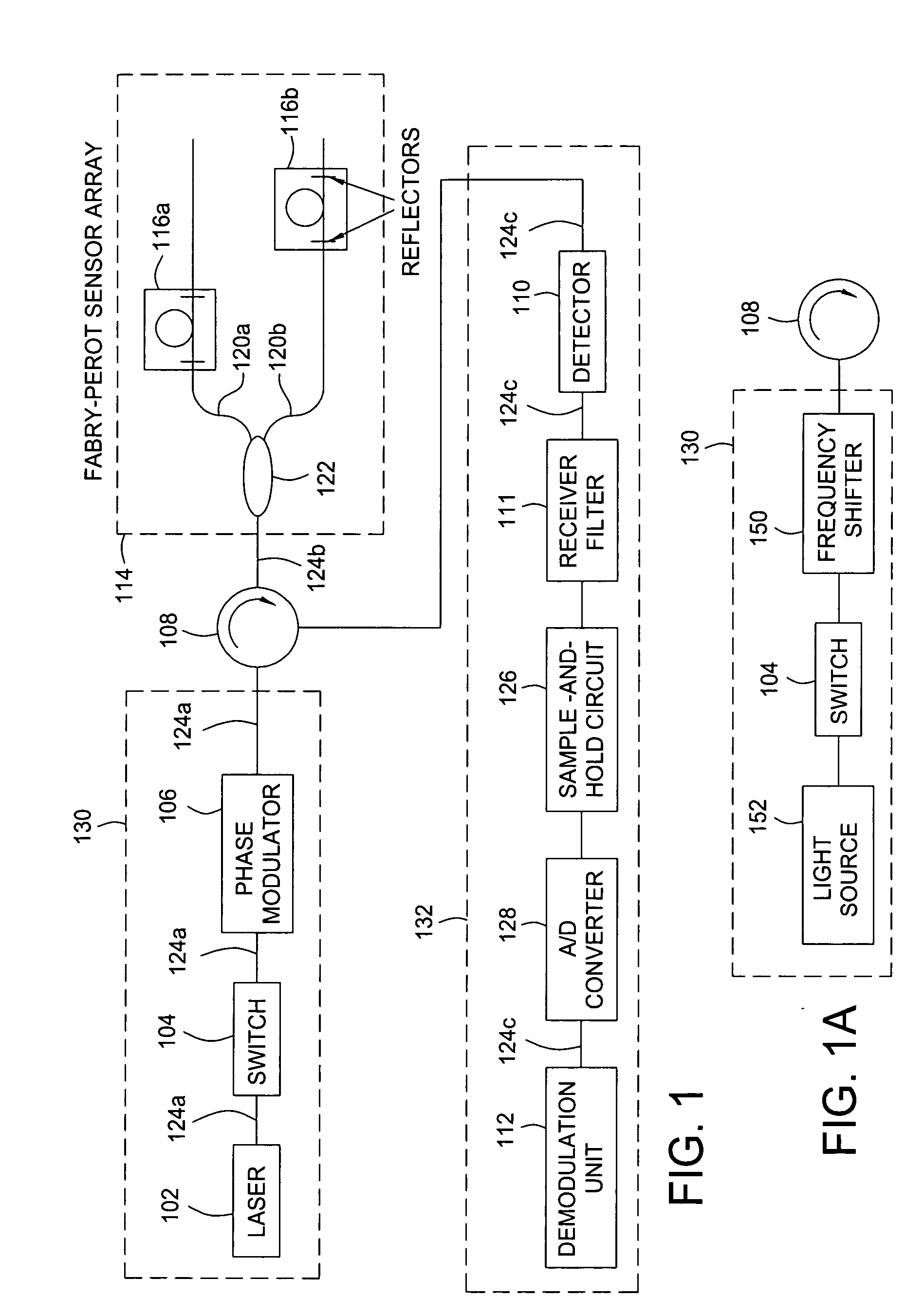
[0027]FIG. 1 illustrates a fiber-optic time-division multiplexing (TDM) interferometric sensor system 100 that incorporates the principles of the present invention. The system 100 includes an array 114 of Fabry-Perot sensors 116, a transmitter unit 130 that produces an interrogation signal for the sensor array 114 and a receiver unit 132 that receives and demodulates the signals from the sensors. The transmitter unit 130 includes a laser 102, a switch 104, and a phase modulator 106, while the receiver unit 132 comprises a detector 110, a receiver filter 111 that suppresses frequency components in the detected optical signal that are outside the band required for demodulation of the sensors, a sample-and-hold circuit 126, an analog to digital (A / D) converter 128 and a demodulation unit 112 that extracts the phase of the individual sensors 116. The Fabry-Perot sensors 116a and 116b are individually formed on optical fibers 120a and 120b that are coupled together by a splitter 122 form...


PUM


Abstract

Unwanted signal components in time-division multiplexed (TDM) systems may lead to crosstalk and noise if these pulses overlap with signal pulses from an interrogated sensor. The crosstalk and noise are dominated by interference between the signal pulses from the interrogated sensor and the unwanted signal components and can be greatly reduced by suppressing this interference signal. The unwanted signal components may include overlapping pulses originating from different sets of interrogation pulses (repetition periods). Modulating the phase or frequency between the repetition periods so that the unwanted interference signal does not appear at frequencies from which the phase of the interrogated sensor is demodulated suppresses this interference. Other unwanted signal components include leakage light during dark periods of the duty cycle of an interrogation signal. Modulating the phase difference between the interrogation signal and the leakage light suppresses the interference between the leakage light and the interrogation signal.

Description

BACKGROUND OF THE INVENTION [0001] 1. Field of the Invention [0002] The present invention generally relates to time division multiplexed interferometric sensors. More specifically, the present invention relates to interrogating interferometric sensors in a manner that improves signal-to-noise ratios. [0003] 2. Description of the Related Art [0004] A interferometric sensor system may comprise a transmitter unit that produces an interrogation signal for the interferometric sensors, a sensor network, and a receiver unit that detects the signals from the sensor network. The sensor network may comprise several optical pathways from its input to its output, and some pairs of optical pathways form sensor interferometers. These optical pathways are called sensor pathways. Each sensor interferometer comprises a sensor and lead paths, the parts of the two sensor pathways that are not common define the sensor, while the common parts define the lead paths. In a fiber optic sensor network the le...

Claims


Application Information

Patent Timeline
Patent Type & Authority Applications(United States)
IPC IPC(8): G01B9/02
CPCG01D5/3539G01D5/35312G01D5/35303G01D5/35383H04J3/06
Inventor WAAGAARD, OLE HENRIKRONNEKLEIV, ERLEND
Owner OPTOPLAN
Why Eureka
Try Eureka