[0021] Further, according to the present invention, by incorporating a polarized-light
selective reflection layer that selectively reflects the specific polarized component in the reflection-type screen in the projection screen, it is possible to make the reflection-type screen reflect only approximately 50% of the incoming unpolarized extraneous light and environmental light such as illumination light. This is because the polarized-light
selective reflection layer selectively reflects only the specific polarized component owing to its function of separating polarized light. Consequently, even if the brightness of a bright-indication part such as white-indication part is fixed, it is possible to increase the
image contrast approximately two times by reducing, to approximately half, the brightness of a dark-indication part such as black-indication part. Thus, with a projection
system comprising the above-described projection screen, it is possible to sharply display images even under bright environmental light.
[0022] Furthermore, according to the present invention, if the polarized-light
selective reflection layer contained in the reflection-type screen in the projection screen is made to have a cholesteric
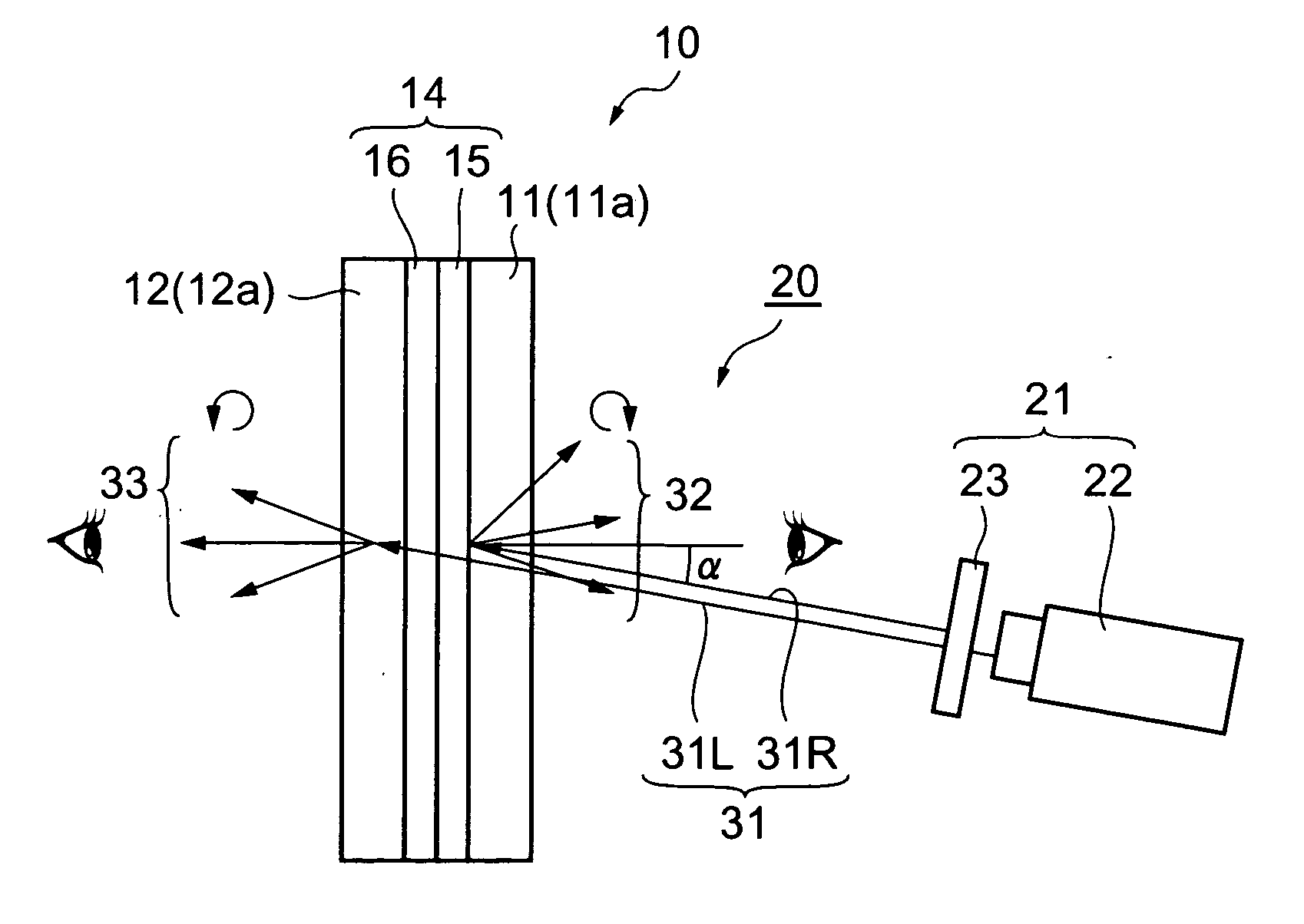
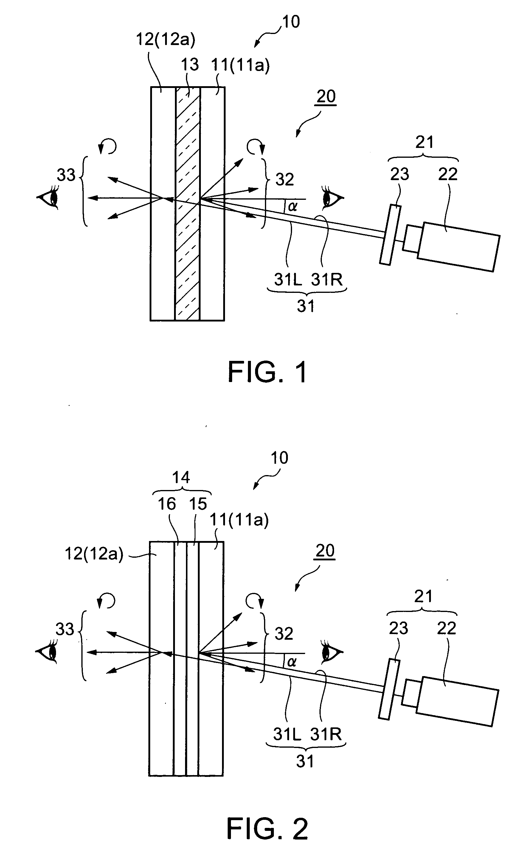
liquid crystalline structure or the like having the function of diffusing light, this layer can reflect the specific polarized component while diffusing it and transmit the other light without diffusing it, so that light passing through the polarized-light selective reflection layer, other than imaging light, is scarcely diffused. Moreover, if a rear-side
diffraction layer formed with a transmission-type
volume hologram that diffracts the light that has passed through the reflection-type screen without being reflected and that has the function of diffusing light is incorporated in the transmission-type screen, the transmission-type screen can transmit, while diffusing, only the light entering at an angle around the angle that meets the
diffraction condition of the rear-side
diffraction layer (the angle that meets the Bragg diffraction condition of the transmission-type
volume hologram), so that light passing through the rear-side diffraction layer, other than imaging light, is scarcely scattered. Namely, if the transmission-type screen is so made, the projection screen diffuses only the light in a specific state of polarization, entering at a specific
angle of incidence, so that only the imaging light in a specific state of polarization, projected on the projection screen at a specific
angle of incidence, is efficiently scattered. For this reason, while imaging light is projected on the projection screen, the images on both sides of the projection screen can be sharply viewed, and when imaging light is not projected on the projection screen, the scene behind the projection screen can be clearly seen through it. Moreover, even when imaging light is projected on the projection screen, the scene behind the projection screen can be clearly seen through those portions of the projection screen on which the imaging light is not projected. Such a projection screen can, therefore, be conveniently used as a see-through projection screen excellent in transparency.
[0023] Furthermore, according to the present invention, when the rear-side diffraction layer formed with a transmission-type
volume hologram or the like is incorporated in the transmission-type screen in the projection screen, the transmission-type screen can diffract only the light, of the light entering from the front of the rear-side diffraction layer, entering at an angle around the angle that meets the diffraction condition of the rear-side diffraction layer (the angle that meets the Bragg diffraction condition of the transmission-type volume hologram), in a direction different from the direction of incidence of the light, irrespective of the state of polarization of the light. Therefore, the imaging light emerging from the rear-side diffraction layer (transmission-type screen) can be clearly viewed from the desired direction, and, in addition, the viewing angle of the imaging light can be readily controlled. In the case where the rear-side diffraction layer has the function of diffusing light, the imaging light that has been separated from environmental light by diffraction is scattered, so that an image can be displayed more sharply. Moreover, the viewing angle of the projection screen can be selected freely and flexibly.
[0024] Furthermore, according to the present invention, by projecting, from one direction, imaging light on one surface of the projection screen from an image projection unit placed on the reflection-type screen side of the projection screen, it is possible to display on the projection screen two identical or different images, one on each side of the screen. It is, therefore, possible to construct a projection
system only by placing one image projection unit on one side of the projection screen, and the constitution of the projection
system is thus extremely simplified.
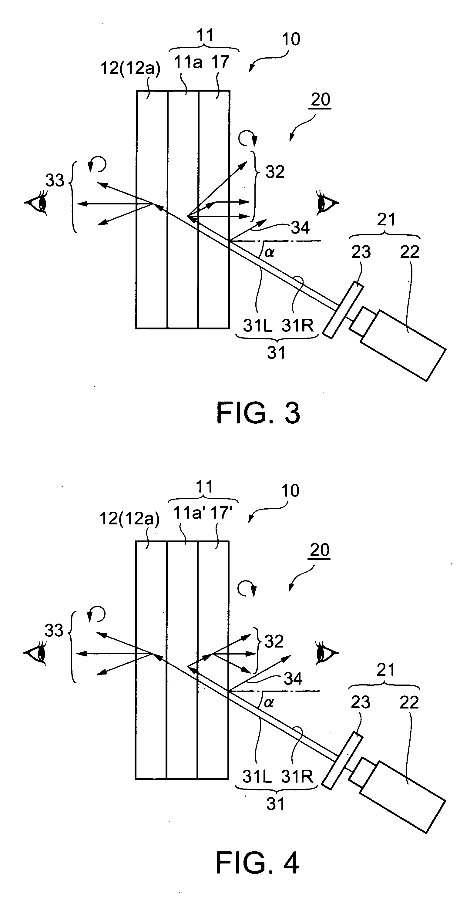
[0025] In the present invention, if a front-side diffraction layer formed with a transmission-type volume hologram or the like that diffracts the light reflected from the polarized-light selective reflection layer to control the direction in which the light emerges from the projection screen is placed on the front of the polarized-light selective reflection layer in the reflection-type screen contained in the projection screen, it becomes possible to diffract light, of the light entering the front-side diffraction layer from its rear, entering at an angle around the angle that meets the diffraction condition of the front-side diffraction layer (the angle that meets the Bragg diffraction condition of the transmission-type volume hologram), in a direction different from the direction of incidence of the light, irrespective of the state of polarization of the light. Therefore, the imaging light emerging from the front-side diffraction layer (reflection-type screen) can be clearly viewed from the desired direction, and, moreover, the viewing angle of the imaging light can be easily controlled. In this case, even if the angle at which the imaging light is incident on the projection screen is made considerably great, it is possible to let the imaging light reflected from the reflection-type screen emerge from the projection screen nearly vertically to it. Consequently, the imaging light reflected from the reflection-type screen in the projection screen and the light reflected, by interfacial reflection, from the front surface of the projection screen (e.g., the surface of the front-side diffraction layer) can be separated from each other with certainty, and it is thus possible to effectively prevent mirroring that is caused by interfacial reflection on the surface of the projection screen. Further, in this case, if the front-side diffraction layer is made so that it has the function of diffusing light, the polarized-light selective reflection layer is not needed to have this function. Furthermore, when both the front-side diffraction layer and the polarized-light selective reflection layer have the function of diffusing light, the
diffusion angle can be made greater by the combination of the function of diffusing light of the former layer and that of the latter layer, and the viewing angle of the projection screen can, therefore, be selected freely and flexibly.
[0026] Furthermore, in the present invention, if a retardation layer that brings a phase shift to the light incident on the polarized-light selective reflection layer is placed on the front of the polarized-light selective reflection layer in the reflection-type screen contained in the projection screen, it becomes possible to eliminate the
distortion or the like of the polarization of light obliquely entering the polarized-light selective reflection layer, and the efficiency of the separation of polarized light by the polarized-light selective reflection layer can thus be increased. Moreover, even when the state of polarization of the light itself projected from the image projection unit is not the same as that of the light to be separated by the polarized-light selective reflection layer, it is possible to optimize the state of polarization of the light that enters the polarized-light selective reflection layer, by properly adjusting the
phase difference the retardation layer has.

