Optical packet exchanger

a packet exchanger and optical technology, applied in the field of optical packet exchangers, can solve the problems of reducing transmission efficiency and transmittable capacity by the amount, and achieve the effect of preventing the reduction of throughput due to multiplexing of an address signal and high modulation speed of an information signal

Inactive Publication Date: 2006-08-17
PANASONIC CORP
View PDF8 Cites 2 Cited by
  • Summary
  • Abstract
  • Description
  • Claims
  • Application Information

AI Technical Summary

Benefits of technology

[0014] Thus, according to the present invention, decrease in throughput due to multiplexing of an address signal is prevented, and the transmission path for an optical packet can be switched based on a simple structure even if the modulation speed for the information signal becomes high.

Problems solved by technology

However, the aforementioned conventional optical packet exchanger has a problem in that, since a data signal to which the address signal corresponding to the information signal is added as a header is used, the transmittable capacity is decreased by the amount corresponding to the address signal; that is, the transmission efficiency is decreased.

Method used


Image

  • Optical packet exchanger
  • Optical packet exchanger
  • Optical packet exchanger

Examples


first embodiment

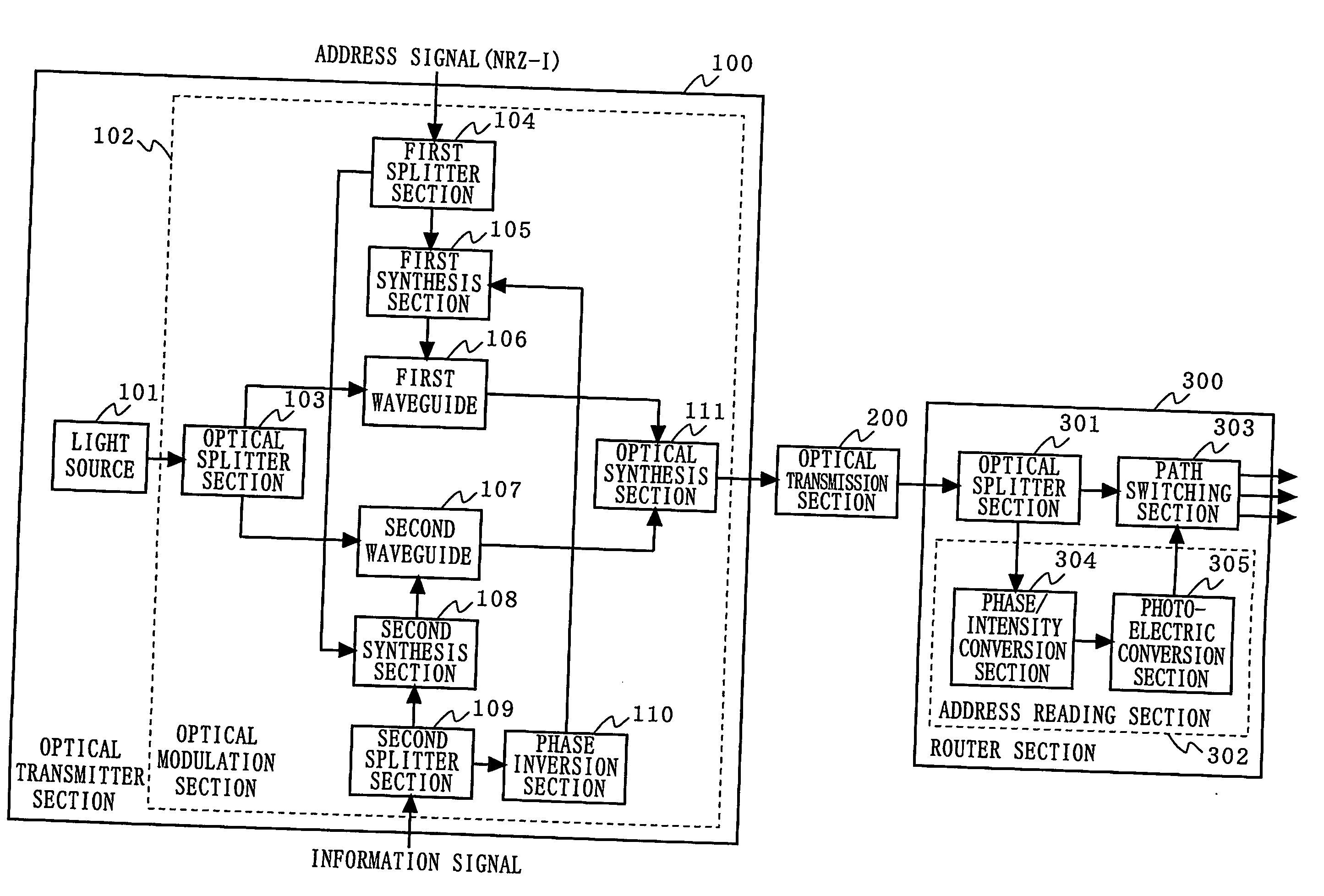
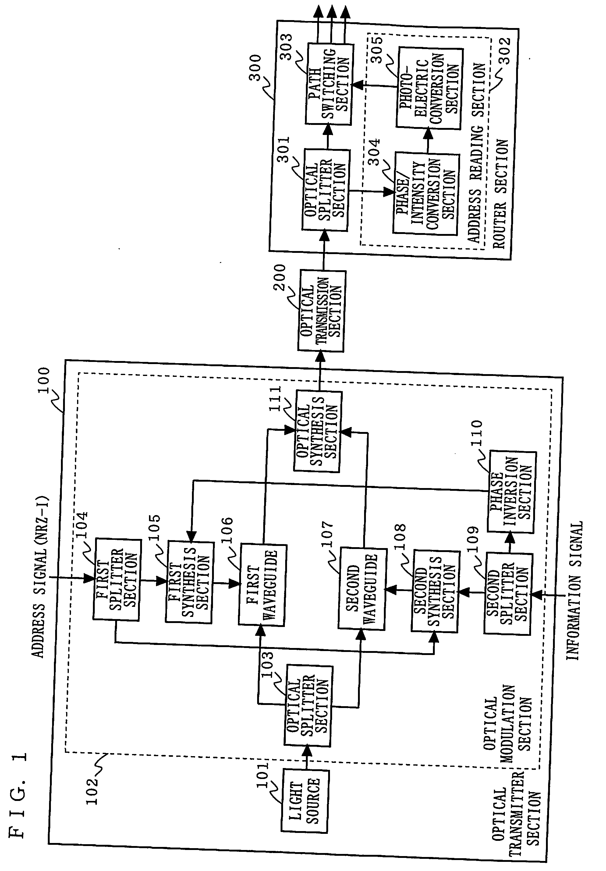
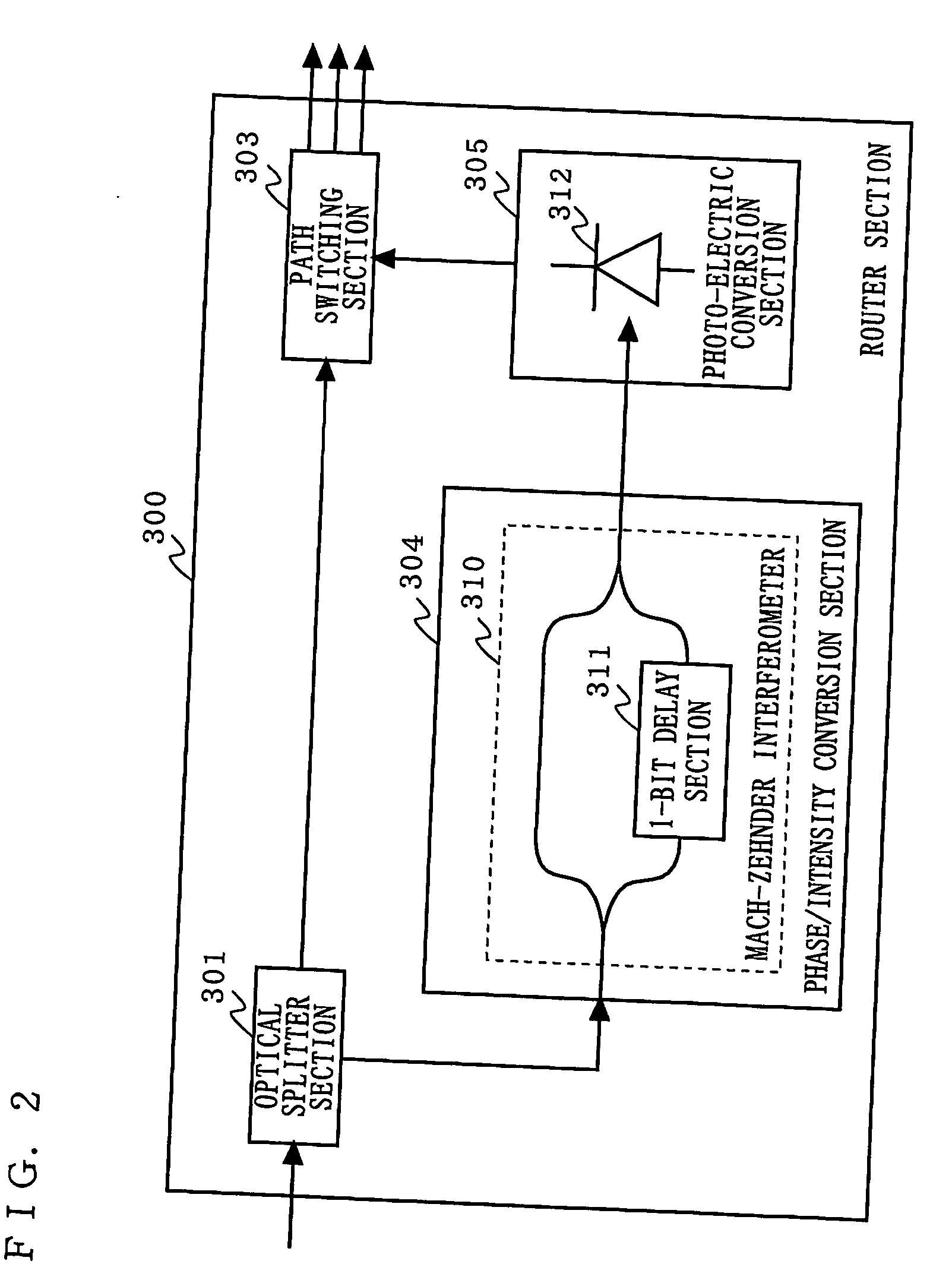
[0026]FIG. 1 is a block diagram illustrating the structure of an optical packet exchanger according to a first embodiment of the present invention. In FIG. 1, the optical packet exchanger according to the first embodiment is composed of an optical transmitter section 100, an optical transmission section 200, and a router section 300. The optical transmitter section 100 comprises a light source 101 and an optical modulation section 102. The optical modulation section 102 includes an optical splitter section 103, a first splitter section 104, a first synthesis section 105, a first waveguide 106, a second waveguide 107, a second synthesis section 108, a second splitter section 109, a phase inversion section 110, and an optical synthesis section 111. The router section 300 comprises an optical splitter section 301, an address reading section 302, and a path switching section 303. The address reading section 302 includes a phase / intensity conversion section 304 and a photoelectric conver...

second embodiment

[0049]FIG. 7 is a block diagram illustrating the structure of an optical packet exchanger according to a second embodiment of the present invention. In FIG. 7, the optical packet exchanger according to the second embodiment is composed of an optical transmitter section 120, an optical transmission section 200, and a router section 300. The optical transmitter section 120 comprises a light signal source 121 and an optical modulation section 122. The light signal source 121 includes a light source 101, a first splitter section 104, a first synthesis section 105, and a first waveguide 106. The optical modulation section 122 includes a second waveguide 107, a second synthesis section 108, a second splitter section 109, and a phase inversion section 110. The router section 300 has the same structure as that of the router section 300 in the first embodiment.

[0050] As seen from FIG. 7, in the optical packet exchanger according to the second embodiment, a phase modulation function using an...

third embodiment

[0051]FIG. 8 is a block diagram illustrating the structure of an optical packet exchanger according to a third embodiment of the present invention. In FIG. 8, the optical packet exchanger according to the third embodiment includes an optical transmitter section 130, an optical transmission section 200, and a router section 300. The optical transmitter section 130 comprises a light signal source 131 and an optical modulation section 132. The light signal source 131 includes a light source 101, a second waveguide 107, a second synthesis section 108, a second splitter section 109, and a phase inversion section 110. The optical modulation section 132 includes a first splitter section 104, a first synthesis section 105, and a first waveguide 106. The router section 300 has the same structure as that of the router section 300 in the first embodiment.

[0052] As seen from FIG. 8, in the optical packet exchanger according to the third embodiment, a phase modulation function using an address ...


PUM


Abstract

An optical packet exchanger is provided which, in a situation where a transmission path for an optical packet is to be switched by using an address signal, prevents the transmittable capacity for the information signal from being decreased, and which facilitates the extraction of the address signal even if the modulation speed for the information signal becomes high. An optical modulation section 102 outputs an optical packet obtained by subjecting output light from a light source 101 to an intensity modulation using an information signal and a phase modulation using an address signal corresponding to a transmission destination for the information, signal. An optical splitter section 301 splits the optical packet received via the optical transmission section 200 into two optical packets. An address reading section 302 reads the address signal from the phase of one of the optical packets output from the optical splitter section 301. Based on the address signal output from the address reading section 302, a path switching section 303 determines an output port for the other optical packet

Description

TECHNICAL FIELD [0001] The present invention relates to an optical packet exchanger, and more particularly to an optical packet exchanger for switching a transmission path for an optical packet signal by using an address signal. BACKGROUND ART [0002] An example of a conventional optical packet exchanger for switching a transmission path for an optical packet signal by using an address signal is a device disclosed in, for example, K. SETO et al., “giga-bit Ethernet textbook”, multimedia tsushin kenkyukai, ASCII corporation, March 1999. FIG. 11 is a block diagram illustrating an exemplary structure of this conventional optical packet exchanger. [0003] In FIG. 11, the conventional optical packet exchanger is composed of an optical transmitter section 1000, an optical transmission section 2000, and a router section 3000. The optical transmitter section 1000 comprises a light source 1001, an optical modulation section 1002, and a data generation section 1003. The router section 3000 comp...

Claims


Application Information

Patent Timeline
Patent Type & Authority Applications(United States)
IPC IPC(8): H04J14/00H04B10/27H04B10/516H04B10/54H04B10/556H04B10/61H04L12/70H04Q11/00
CPCH04Q11/0005H04Q11/0066H04Q2011/0015H04Q2011/0039H04Q2011/0041
Inventor SHIOZAKI, TORUFUSE, MASARU
Owner PANASONIC CORP
Why Eureka
Try Eureka