Substrate transportation device (wire)

a transportation device and substrate technology, applied in transportation and packaging, conveyors, packaging goods types, etc., can solve problems such as unsuitability for use, and achieve the effect of eliminating sagging or drooping of substrates and sufficient strength

Inactive Publication Date: 2006-08-17
AU OPTRONICS CORP
View PDF16 Cites 10 Cited by
  • Summary
  • Abstract
  • Description
  • Claims
  • Application Information

AI Technical Summary

Benefits of technology

[0008] The present invention relates to a transportation device for storing, supporting and transporting a substrate such as a glass tray during manufacture, so that the substrate does not bend or come in contact with the housing or cassette of the transportation device. The transportation device is one stage in a cassette station system for manufacturing and transporting glass trays. Glass trays are used as an example, however, the present invention is not limited to transporting glass trays, and any kind of substrate can benefit from the transportation device of the present invention. Glass trays include, for example, thin film transistor liquid crystal display panels (TFT-LCD), which are used in applications ranging from mobile telephones to computer monitor screens to flat panel televisions. As such, sagging and bending due to weak support for the middle of the glass tray can result in physical damage to or permanent deformation of the glass tray, making the tray unsuitable for use. Among other things, the substrate transportation device of the present invention provides a plurality of supporting members such as, for example, wires of adjustable rigidity to support the substrate in the housing, thereby providing sufficient strength to the supporting members that eliminate sagging or drooping of the substrate in the housing.

Problems solved by technology

As such, sagging and bending due to weak support for the middle of the glass tray can result in physical damage to or permanent deformation of the glass tray, making the tray unsuitable for use.

Method used


Image

  • Substrate transportation device (wire)
  • Substrate transportation device (wire)
  • Substrate transportation device (wire)

Examples


Embodiment Construction

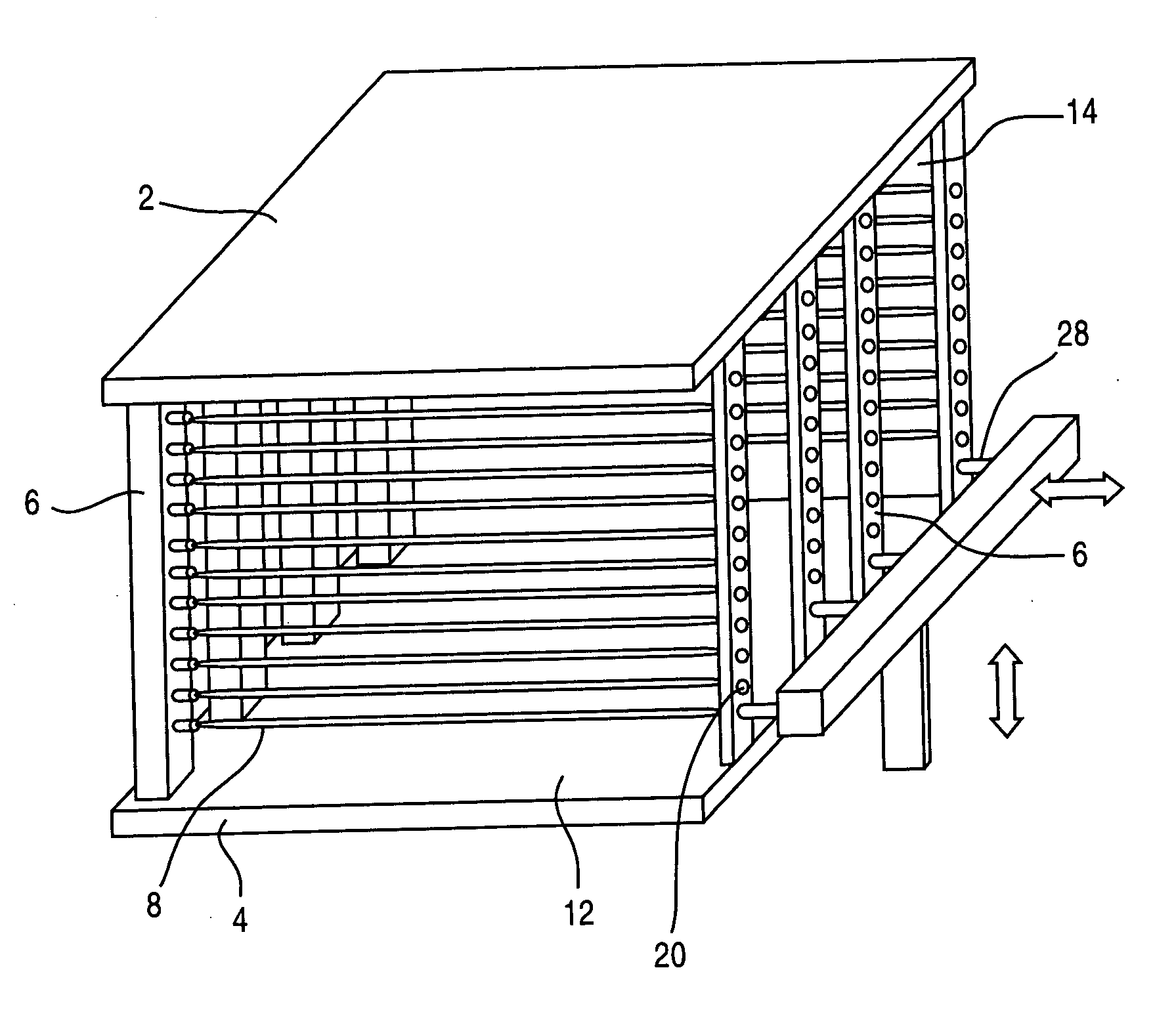
[0025] The present invention is directed to a substrate transportation device for transporting and supporting such as, for example a glass tray, during manufacture. A glass tray can include a thin film transistor liquid crystal display panel.

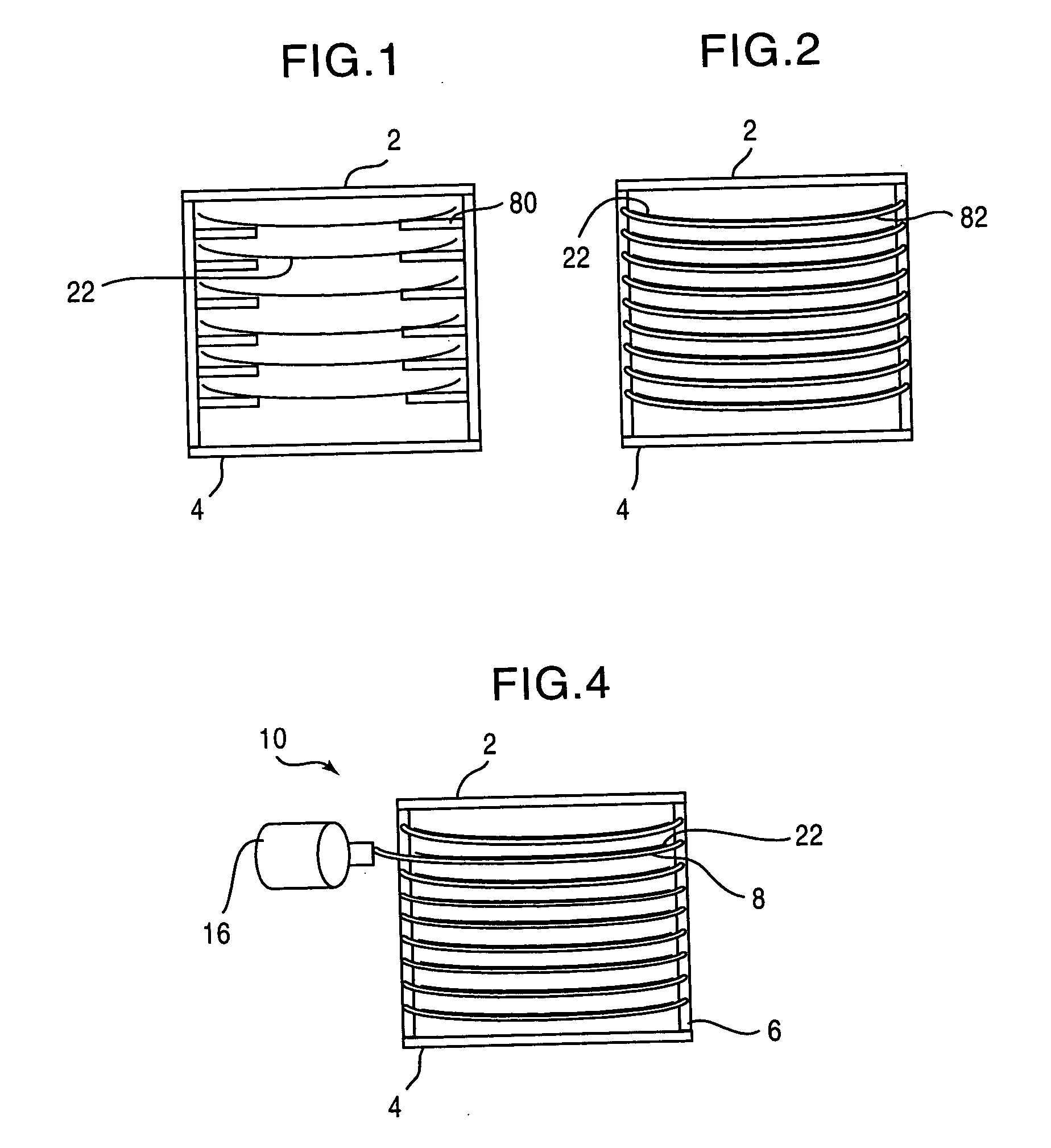
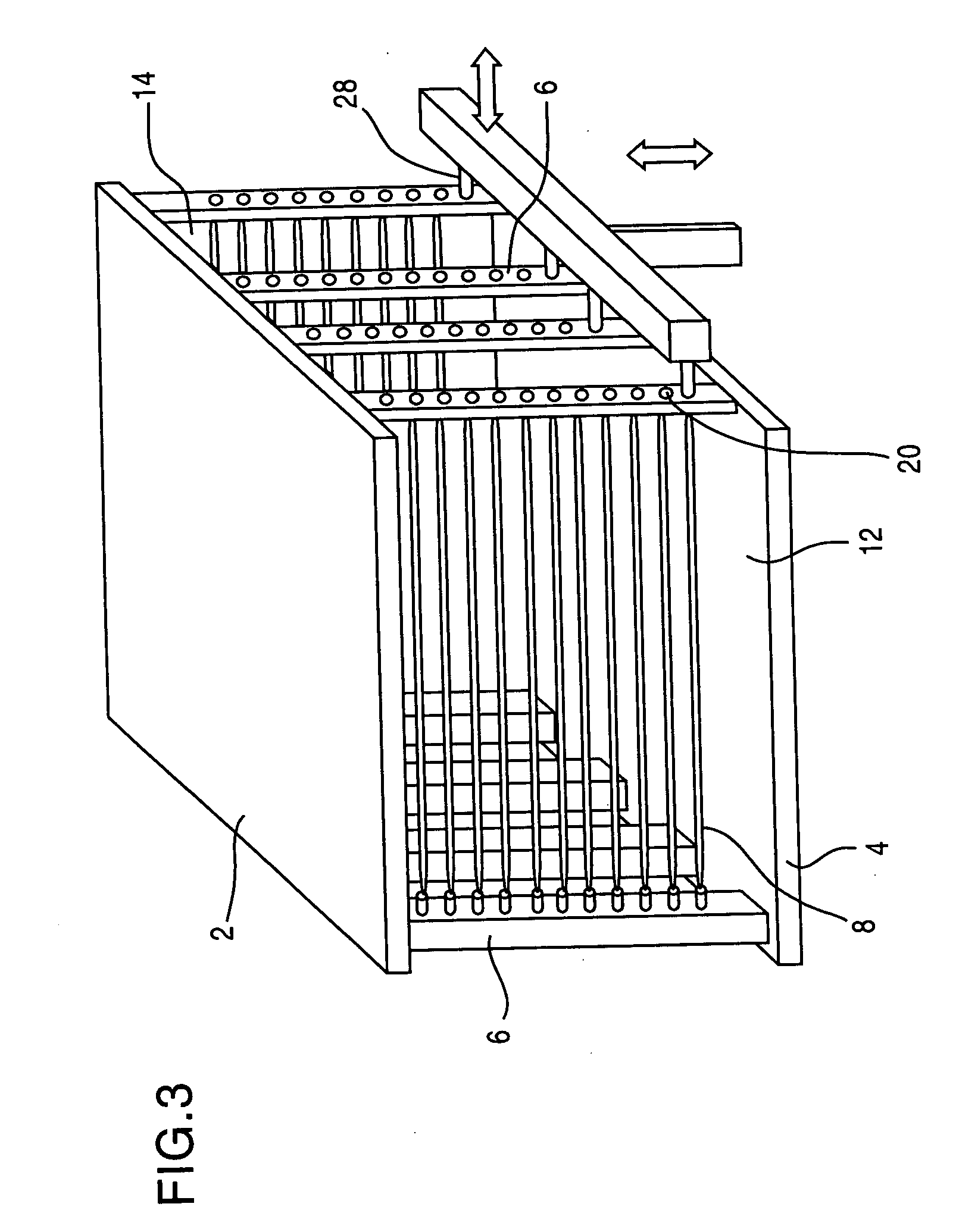
[0026] As shown in FIG. 4, the substrate transportation device includes a housing 10 for transporting a substrate 22. The cassette or housing 10 includes an upper surface 2, a lower surface 4, and opposing sidewalls 6 which can be formed as a plurality of columns. As shown in FIG. 3, there is a rear opening 14 through which the substrate 22 enters the housing 10 and a front opening 12 through which the substrate 22 exits the housing 10. The housing 10 is illustrated in FIGS. 3 and 4 as having a rectangular shape, however, the housing can be any other appropriate shape. The housing 10 and sidewalls 6 can be made of any material including, but not limited to a metal tube, engineering plastic, or a fiber reinforced plastic tube.

[0027] Supporting ...


PUM


Abstract

A substrate transportation device includes a housing formed of an upper surface, a lower surface, and opposing sidewalls. The housing has a rear opening through which the substrate enters the housing and a front opening through which the substrate exit the housing. A plurality supporting members are disposed within the housing and operatively connected to the opposing sidewalls which can be formed as a plurality of columns. A motor and motor shaft transmit a rotational force to an axle system, which transmits rotational force to the supporting members to transfer the substrate into or out of the housing randomly.

Description

BACKGROUND OF THE INVENTION [0001] 1. Field of the Invention [0002] This invention relates to a substrate transportation device. More specifically, the present invention relates to a substrate transportation device for transporting a material, for example, a glass tray from one location to another, and providing sufficient support for the entire body of the tray, and thereby improving the transportation of the substrate in an efficient and timely manner. [0003] 2. Description of the Related Art [0004] Automation and robotics are used in substrate transportation to improve the efficiency of transportation, and serve to reduce human contamination of the glass tray, used in the contamination-sensitive thin film transistor liquid crystal displays (TFT-LCD). Such a glass tray is manufactured in clean-room environments. [0005] When a large glass tray is placed in a housing by a robotic apparatus, the tray must be supported underneath. This is often accomplished by a grid structure. As sho...

Claims


Application Information

Patent Timeline
Patent Type & Authority Applications(United States)
IPC IPC(8): B65G1/00
CPCB65D85/48B65G49/062B65G49/067B65G49/068B65G2249/02H01L21/673
Inventor LIU, SHIANG-CHIANGLU, TSUNG-LINCHEN, YING-CHI
Owner AU OPTRONICS CORP
Why Eureka
Try Eureka