Methods of forming mask patterns, methods of correcting feature dimension variation, microlithography methods, recording medium and electron beam exposure system

a mask pattern and feature dimension technology, applied in the field of mask pattern formation, can solve the problems of non-uniformity of critical dimension throughout the pattern, change the critical dimension, fail to account, etc., and achieve the effect of reducing beam deflection effect and reducing backscattering

Inactive Publication Date: 2006-08-17
MICRON TECH INC
View PDF13 Cites 31 Cited by
  • Summary
  • Abstract
  • Description
  • Claims
  • Application Information

AI Technical Summary

Benefits of technology

[0012] In one aspect the invention encompasses an electron beam exposure system. The system includes an electron beam source and a movable stage for supporting a substrate. The system additionally includes a processor which contains programming configured to cause processing circuitry to access exposure data, divide the exposure pattern into regions, determine a dose correction for each region to alleviate backscattering effects and alleviate beam deflection effects, and generate a corrected exposure pattern to apply a corrected dose for each region. The system additionally includes a controller which is configured to direct electrons emitted by the electron beam source to expose the layer of resist on a mask blank in accordance with the corrected exposure pattern.

Problems solved by technology

The variance in critical dimension can be non-uniform throughout the pattern such that some feature dimensions in a particular area of the pattern are closer to the intended feature dimension than those in other areas of the pattern.
This unintentional exposure due to backscattering can change the critical dimension of an intended pattern producing a “re-scattering” or fogging effect.
Although the symmetrical correction model is somewhat effective for correcting CD variations, such fails to account for additional factors that may contribute toward the fogging effect and thereby fails to produce global CD uniformity throughout the pattern.

Method used


Image

  • Methods of forming mask patterns, methods of correcting feature dimension variation, microlithography methods, recording medium and electron beam exposure system
  • Methods of forming mask patterns, methods of correcting feature dimension variation, microlithography methods, recording medium and electron beam exposure system
  • Methods of forming mask patterns, methods of correcting feature dimension variation, microlithography methods, recording medium and electron beam exposure system

Examples


Embodiment Construction

[0035] This disclosure of the invention is submitted in furtherance of the constitutional purposes of the U.S. Patent Laws “to promote the progress of science and useful arts” (Article 1, Section 8).

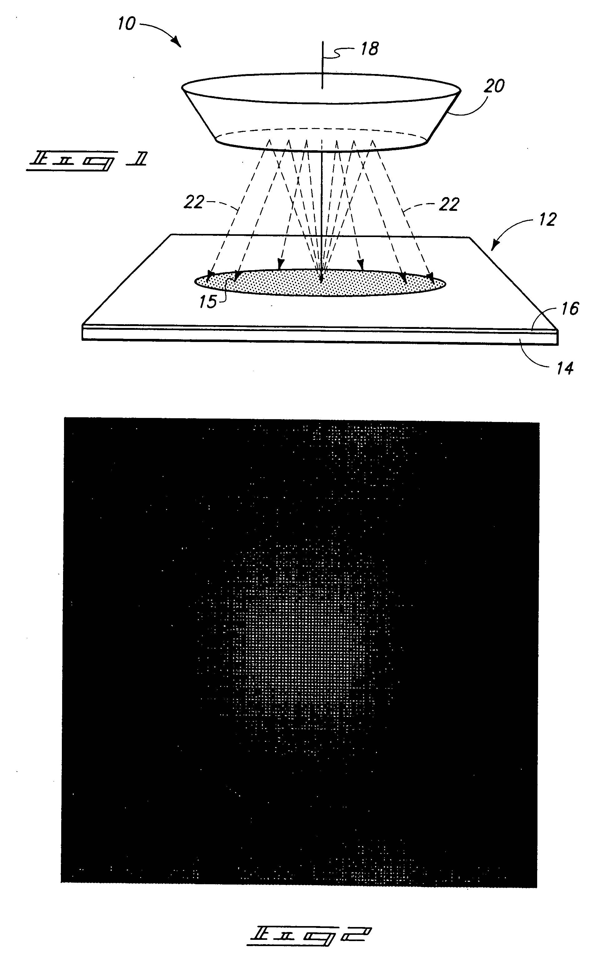
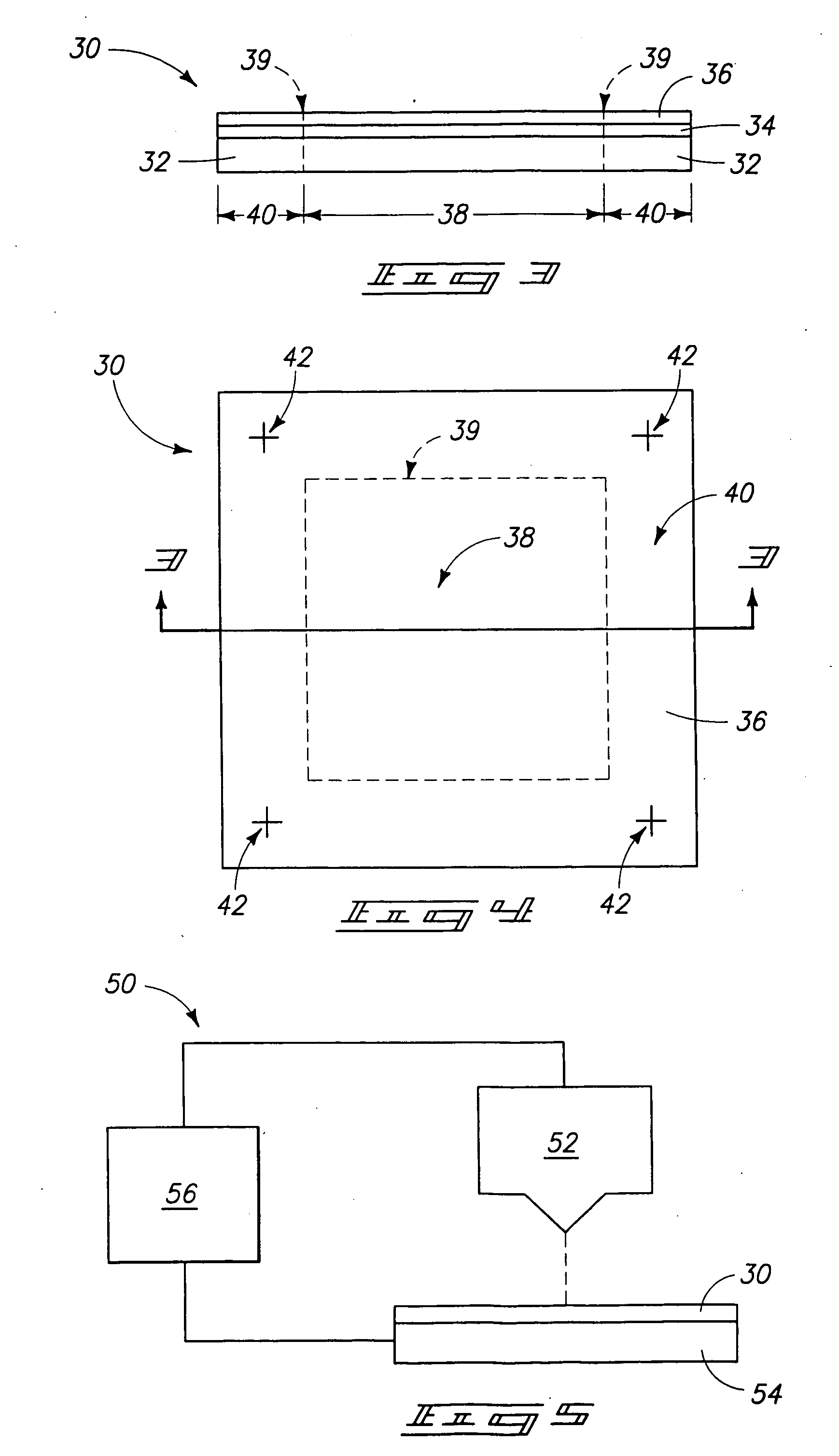
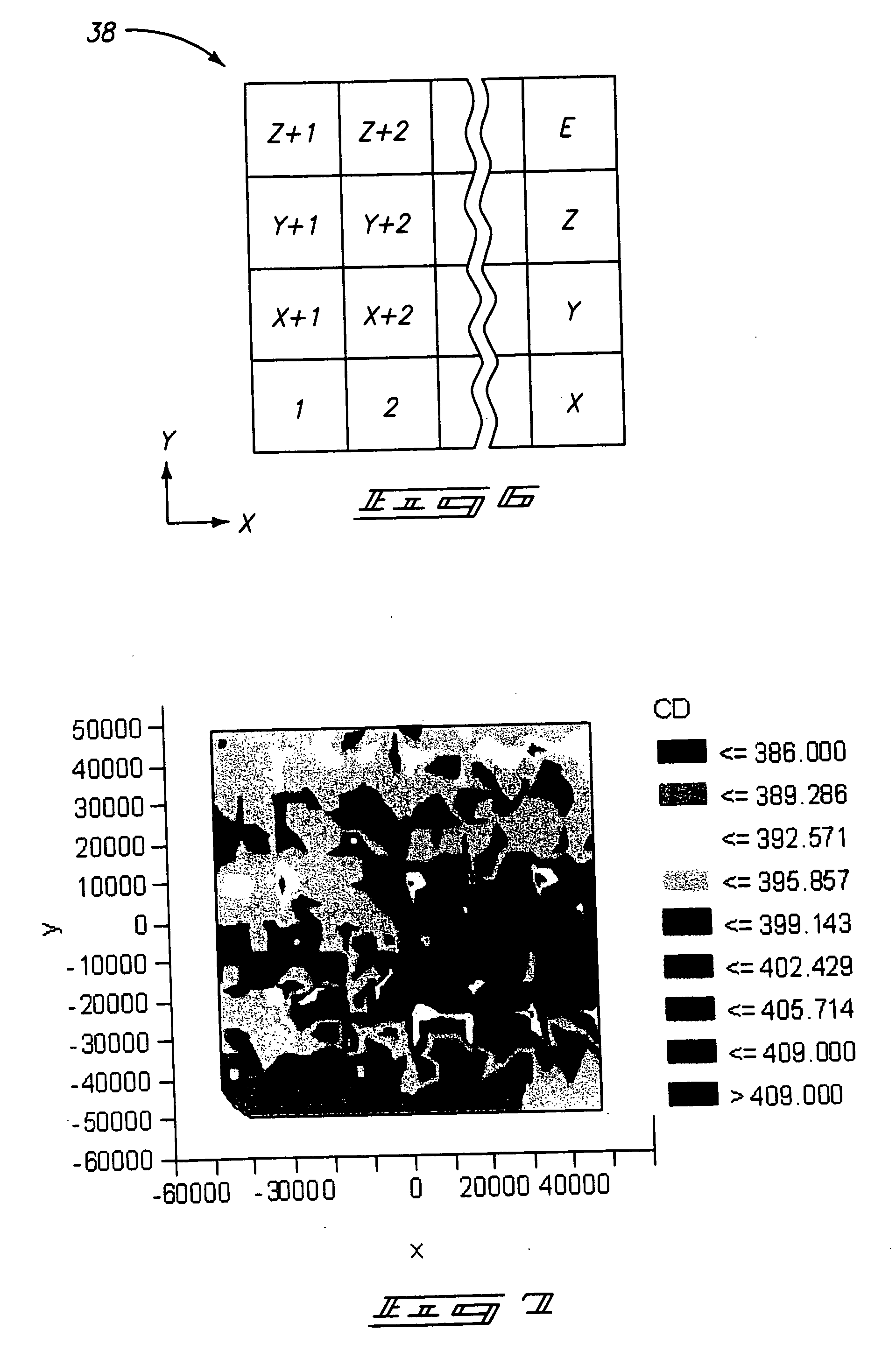
[0036] The present invention relates to methodology and systems for correcting feature dimension variation which can occur during exposing a resist to form a feature pattern. In particular aspects, the invention pertains to correcting or alleviating feature dimension variation during electron beam lithography. It is to be understood however, that the techniques and methodology described herein can be adapted for application to other lithography techniques. Further, although the invention is described in terms of forming a mask or reticle the invention additionally contemplates utilization of the described aspects of the invention during alternative patterning application such as, for example, patterning a semiconductive wafer.

[0037] As discussed in the background section of this descri...


PUM

PropertyMeasurementUnit
stripe heightaaaaaaaaaa
stripe lengthaaaaaaaaaa
stripe heightaaaaaaaaaa

Abstract

The invention includes methods of forming reticles. A mask blank is provided having a plurality of regions defined within a main-field area. Exposure to an electron beam is initiated at an initial locus within an interior region of the main-field. The invention includes a method of correcting feature dimension variation. A mask blank is patterned utilizing a first dose correction component and feature dimension variance is determined. The variance is utilized to determine a second correction component which is added to the first dose correction component to create an enhanced dose correction. The invention includes a recording medium and a system comprising the recording medium. The medium contains programming configured to cause processing circuitry to: access data defining a design pattern; obtain error data pertaining to feature dimension variation; generate correction data; produce data defining a corrective pattern; and apply the corrective pattern during an exposure event.

Description

TECHNICAL FIELD [0001] The invention pertains to methods of forming mask patterns, methods of correcting feature dimension variation, microlithography methods, recording medium and microlithography exposure systems. BACKGROUND OF THE INVENTION [0002] Radiation patterning tools are utilized to pattern radiation during, for example, semiconductor processing. The patterned radiation (such as, for example, UV light) is projected against a radiation-imagable material such as, for example, photoresist and utilized to create a pattern in the radiation-imagable material. The utilization of a patterned radiation for forming a desired pattern in a radiation-imagable material is typically referred to as photolithography. The radiation-patterning tool can be referred to as a photomask or reticle. The term “photomask” is traditionally understood to refer to masks which define a pattern for an entirety of a wafer, and the term “reticle” is traditionally understood to refer to a patterning tool wh...

Claims


Application Information

Patent Timeline
Patent Type & Authority Applications(United States)
IPC IPC(8): G03F1/00G03C5/00G21G5/00A61N5/00
CPCG03F1/78G03F7/2061G03F7/2063H01J2237/31764H01J2237/31769
Inventor YANG, BAORUICHANCE, RANDAL W.
Owner MICRON TECH INC
Why Eureka
Try Eureka