
Orientation device for surgical implement

a technology of orientation device and surgical implement, which is applied in the field of surgical operations, can solve the problems of insufficient present techniques, less developed techniques designed to improve them, and complicated orientation of the acetabular component, so as to facilitate and improve the training of surgeons, improve patient positioning, and increase objectivity

Inactive Publication Date: 2006-08-17
SAN TECH SURGICAL
View PDF10 Cites 242 Cited by
  • Summary
  • Abstract
  • Description
  • Claims
  • Application Information

AI Technical Summary

Benefits of technology

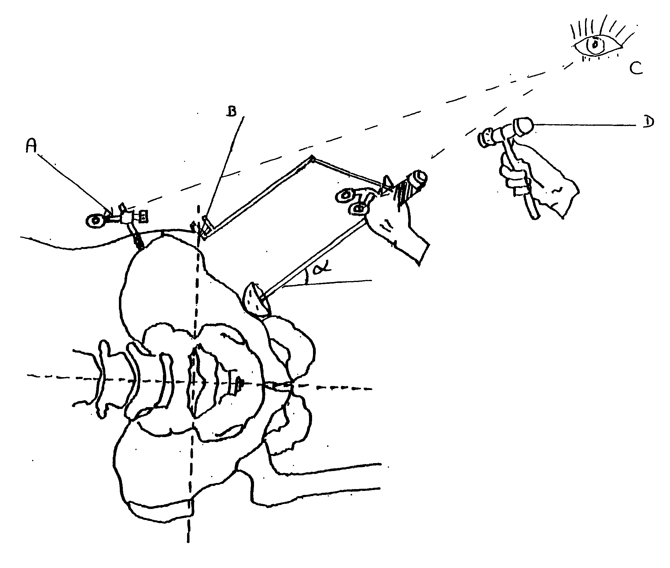
[0021] Preferably the orientation device is a guide that can be easily released from the instrument so the instrument fixing means are adapted to allow a quick fixation or release of the orientation device to / from the instrument. The orientation device may be also permanently fixed to the instrument or be an instrument unto itself.
[0047] Refining the instruments used for orientation of the components: making it easier to use allowing use by looking at it from different angles.

Problems solved by technology

Orientation of the acetabular component is far more complicated, and techniques designed to improve it are far less developed.
Some of the present techniques are inadequate due to the complexity.
The literature has shown a lack of accuracy even among experienced surgeons when estimating intraoperative orientation of the acetabular cup with standard techniques.
Some techniques developed for computer assisted surgery are promising but present limitations of their own and it may be some time before patients can benefit.
Its world wide availability is limited due to high costs and special training required.
The initial position of the pelvis in three planes (Yaw, Roll and Pitch) is ignored and therefore can lead to errors.
The second problem with standard orientation devices is the assumption that the orientation of the pelvis in terms of flexion / extension is always the same with respect to the axis of the table.
Additionally, standard mechanical orientation devices rely on visual references and therefore lack precision.
In Minimally invasive surgery (MIS), small surgical incisions make it even more difficult to obtain adequate orientation of the components.
Many surgeons orient the acetabular component through subjective “feeling”, a technique that has also been shown in the literature to be highly inaccurate and imprecise even in the most experienced hands.
Studies in saw bone models comparing free hand techniques and standard mechanical orientation devices with computer assisted navigation have clearly shown the lack of accuracy and precision of both techniques.
Lack of optimal orientation of both components acetabular cup and shaft as a couple, has been shown to result in limited range of motion due to impingement which leads to dislocation, early wear and loosening of the components.
The situation has lead to the use of imperfect techniques associated with prosthetic acetabular implantation, often involving the use of manually operated instrumentation which rely only on the surgeons hand and eye coordination to install the implant and occasionally relying on visual markers.

Method used


Image

  • Orientation device for surgical implement
  • Orientation device for surgical implement
  • Orientation device for surgical implement

Examples


Embodiment Construction

[0057] The invention will be discussed in a more detailed way here below. To this effect some examples, together with corresponding drawings, will be used.

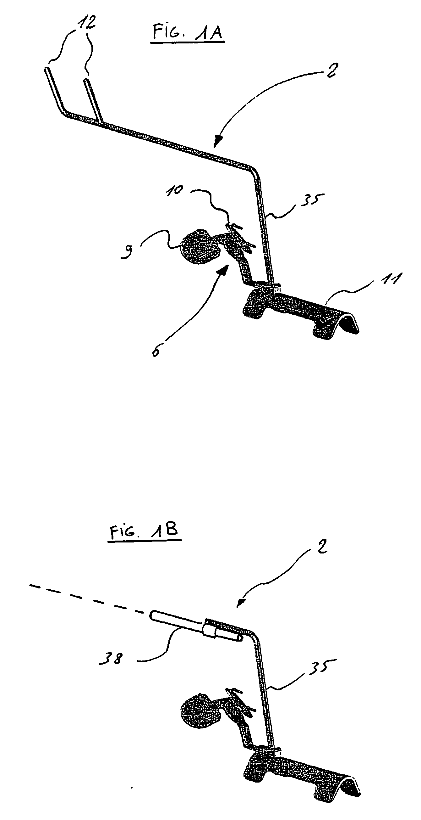
[0058]FIG. 1A shows an embodiment of a guide according to the invention.

[0059]FIG. 1B shows an alternate embodiment of the guide, with a laser pointer.

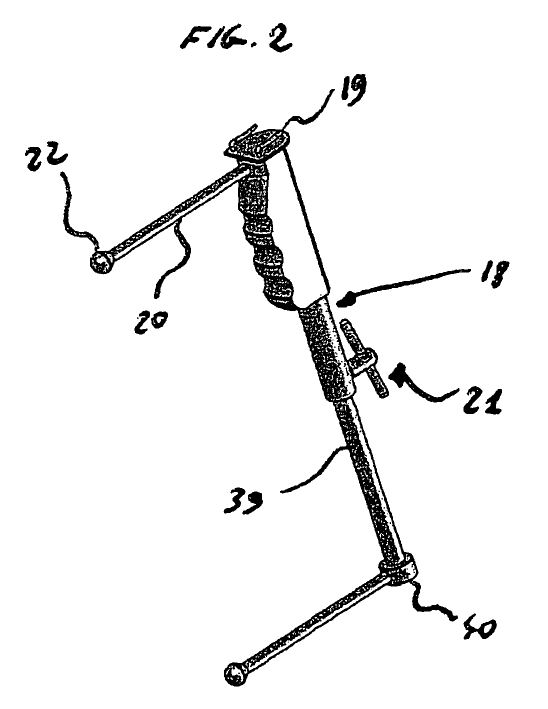
[0060]FIG. 2 shows a pelvic positioner

[0061]FIG. 3 shows the pelvic positioner of FIG. 2 from above with a bubble level.

[0062]FIG. 4 shows the pelvic positioner of FIG. 2 being placed close to a pelvis.

[0063]FIG. 5 shows the guide of FIG. 1 in use.

[0064]FIG. 6 is an enlarged view of the guide of FIG. 1 in use.

[0065]FIG. 7 illustrates the different operating actions when using the guide of FIG. 1.

[0066]FIG. 8 is an exploded view of a calibrating apparatus.

[0067]FIG. 9 shows the calibrating apparatus of FIG. 8 in use with the guide of FIG. 1. FIG. 10 shows a pelvic orientation witness without its bubble level.

[0068]FIG. 11 shows a pelvic orientation witness linked to a pelv...


PUM


Abstract

Orientation device for surgical use includes a frame and a level device attached to the frame. The feature may be oriented with a reference such as the Antero Superior Iliac Spine, the acetabulum or the operating table to position the pelvis or the device. The level device is adapted to define a reference plane. The device thus allows precise orientation with respect to the pelvis through use of a reference plane.

Description

FIELD OF THE INVENTION [0001] The invention relates to the field of surgical operations and in particular to methods and apparatuses for correctly positioning a surgical implement (a surgical tool, prosthesis or implant). [0002] The invention is in particular, but not exclusively, useful for accurately aligning an acetabular prosthetic element. BACKGROUND OF THE INVENTION [0003] Improved orthopaedic procedures have made joint replacement common practice. In total hip arthroplasty, both the femoral or ball aspect of the joint as well as the acetabular or socket portion are replaced with prosthetic implants. Several patent and non-patent references exist in this field. [0004] Orientation of the femoral stem is universally considered as less complex. Orientation of the acetabular component is far more complicated, and techniques designed to improve it are far less developed. Some of the present techniques are inadequate due to the complexity. The literature has shown a lack of accuracy...

Claims


Application Information

Patent Timeline
Patent Type & Authority Applications(United States)
IPC IPC(8): A61B17/90A61B17/17A61B19/00A61F2/02A61F2/34A61F2/46
CPCA61B17/1746A61B2019/468A61F2/34A61F2/4609A61F2/4657A61F2002/30538A61F2002/4668A61F2250/0006A61F2002/4687A61B2090/068
Inventor ECHEVERRI, SANTIAGO
Owner SAN TECH SURGICAL
Learn More