

Flameless boiler
- Summary
- Abstract
- Description
- Claims
- Application Information
AI Technical Summary
Benefits of technology
Problems solved by technology
Method used
Image

Examples
Embodiment Construction
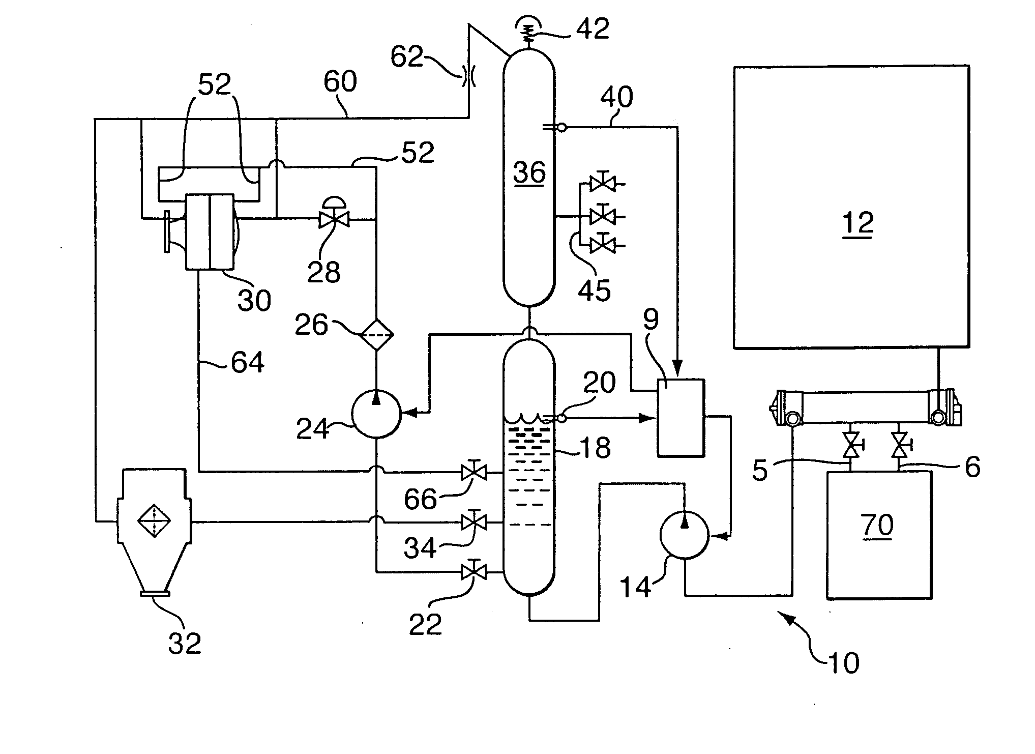
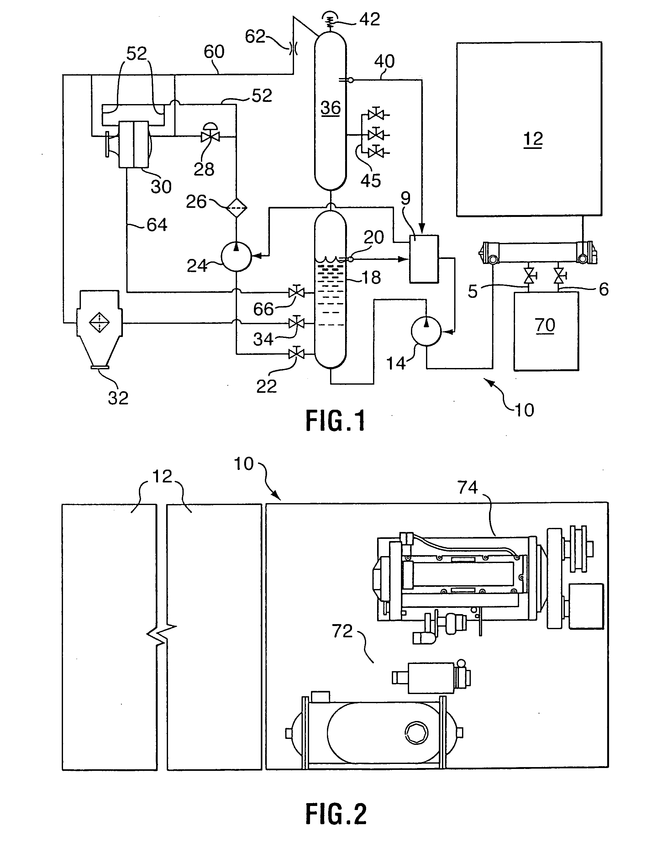
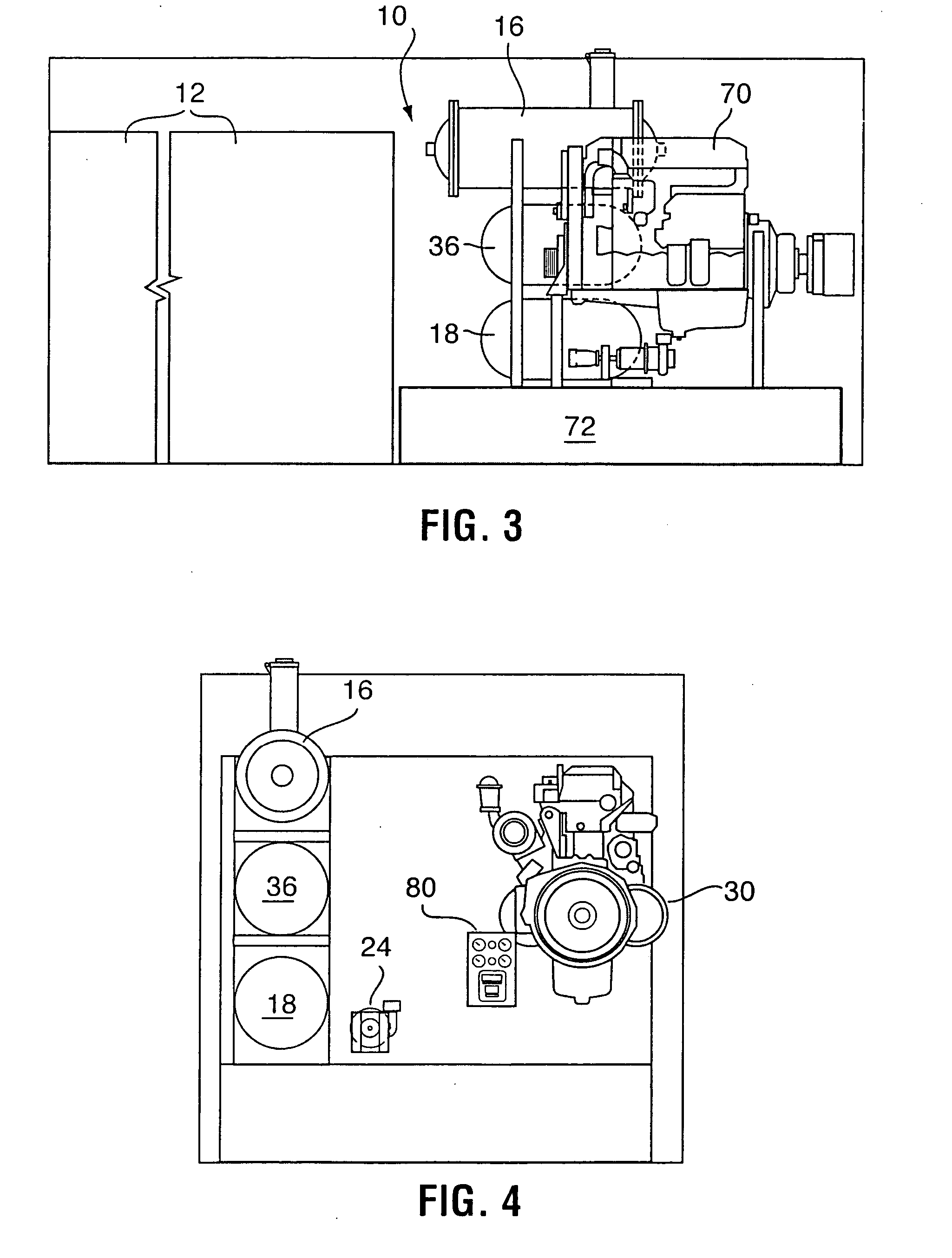
[0017] Reference will now be made to FIG. 1 for a more detailed description of a flameless boiler unit 10. Flameless boiler unit 10 is preferably capable of producing 2.5 million BTU / hr and captures this heat from three sources: engine coolant; exhaust gases; and the use of excess engine horsepower to provide shear heat in the heat transfer fluid, which in this application will normally be water boiled to produce steam.
[0018] Heat from engine 70 is transferred to the engine's cooling system in which the coolant will be water, glycol or a mixture of the two. The heated coolant flows through line 5 to a heat exchanger 16, such as a shell and tube heat exchanger well known in the art, and returns to the engine via line 6. Both lines 5 and 6 can be valved to control the flow of coolant from the engine through exchanger 16.
[0019] Cold water for the present system is stored in a storage tank 12. A pump 14 pumps water from storage tank 12 through engine coolant heat exchanger 16. Since t...
PUM
 Abstract
Description
Claims
Application Information