
Transportable holding tank for stripe removal system

a technology of stripe removal and holding tank, which is applied in the direction of cleaning equipment, cleaning using liquids, cleaning equipment, etc., can solve the problems of equipment gumminess, unsatisfactory surface removal of marking material, and inability to remove markings, etc., and achieve the effect of continually reducing the amount of capacity able to be regained

Inactive Publication Date: 2006-08-24
CROCKER JAMES P
View PDF24 Cites 22 Cited by
  • Summary
  • Abstract
  • Description
  • Claims
  • Application Information

AI Technical Summary

Benefits of technology

[0014] It is an objective of this invention to provide a vacuum recovery truck mounted stripe removal system having a compact unit for safe, fast over-the-road travel to job sites in a single truck construction.
[0020] It is yet another object of this invention to provide a collection / filter receptacle for the removed materials for ease of disposal and the release of filtered wastewater. This allows an operator to easily regain all of the available capacity not occupied by paint or road debris within the vacuum chamber by simply releasing a dump valve. All of the solid debris is retained until such time as the vacuum chamber is completely full. The amount of capacity able to be regained will be continually diminished as the vacuum tank fills with debris, and will eventually reach a point of inefficiency at which point it must be dumped. When the material is dumped, it is dumped as a semi-dried, dewatered debris in which the wastewater is not mixed with the debris.

Problems solved by technology

However, the use of these carbide teeth and grinding wheels results in an undesirable trench or groove in the road.
When polymers such as paint are used for roadway marking, the surface of the pavement is penetrated from ⅛-⅜ inch, so that mere surface removal of the marking material is not sufficient to remove the marking.
While this type of device is effective for removal of markings, they often create excessive heat which may melt thermoplastic materials causing equipment to gum up.
Unfortunately, these devices must remove a portion of the pavement material to effectively remove the marking, thereby leaving unsightly and potentially dangerous grooves in the pavement.
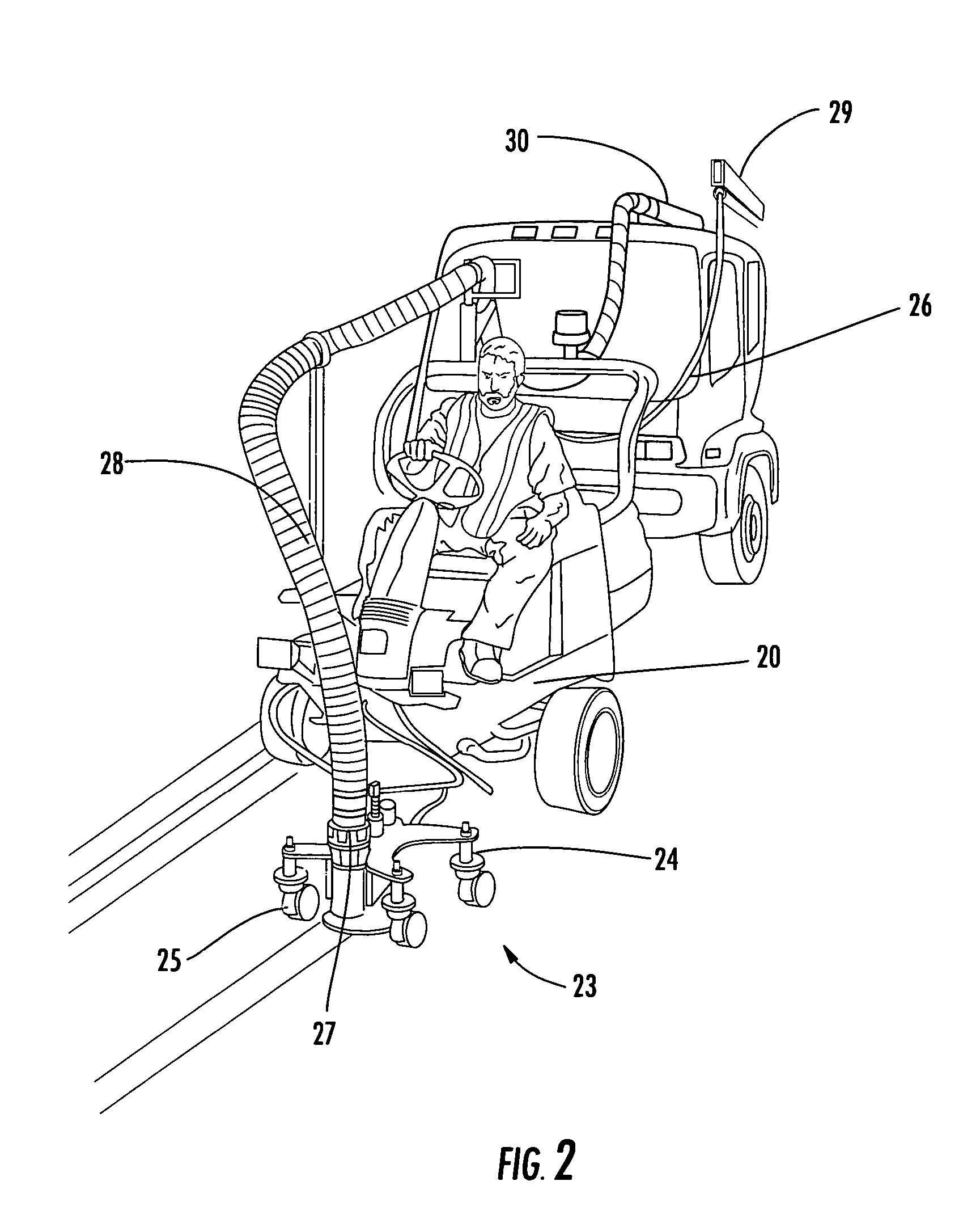
Because of the position of the driver and the cab body of the prime-mover, it is difficult for the operator to see the blast head's position with regard to the stripes on the pavement.
Obtaining clear vision requires the driver to lean out of the driver's side window, resulting in fatigue and other non ergonomically efficient factors.
Positioning the blast head to the passenger side of the prime mover is performed manually with some difficulty and greatly complicating the driver's ability to view the path of the blast head.
In addition, due to the length of the extension holding the blast head, the angular off-set, and the swivel of the casters, the movement of the wheel of the truck is not directly related to the path of the blast head further complicating operation.
A problem associated with the STRIPEJET device relates to the construction of the blast head mounting assembly.
This construction makes the tractor too long for transport on a truck in a transverse orientation.
Transport of the tractor aligned with the longitudinal centerline of the truck requires a substantial amount of bed space, making a one truck stripe removal system impracticable.
One problem with the prior art is the inability to place a suitable amount of equipment upon the bed of a single truck to complete a marking removal task.
A portion of this shortcoming stems from the inability to orient a tractor in a transverse manner with respect to the longitudinal centerline of the truck for transport.
As such these tanks occupy a significant amount of bed space, which obviously limits the amount of equipment that can be transported on a single truck.

Method used


Image

  • Transportable holding tank for stripe removal system
  • Transportable holding tank for stripe removal system
  • Transportable holding tank for stripe removal system

Examples


Embodiment Construction

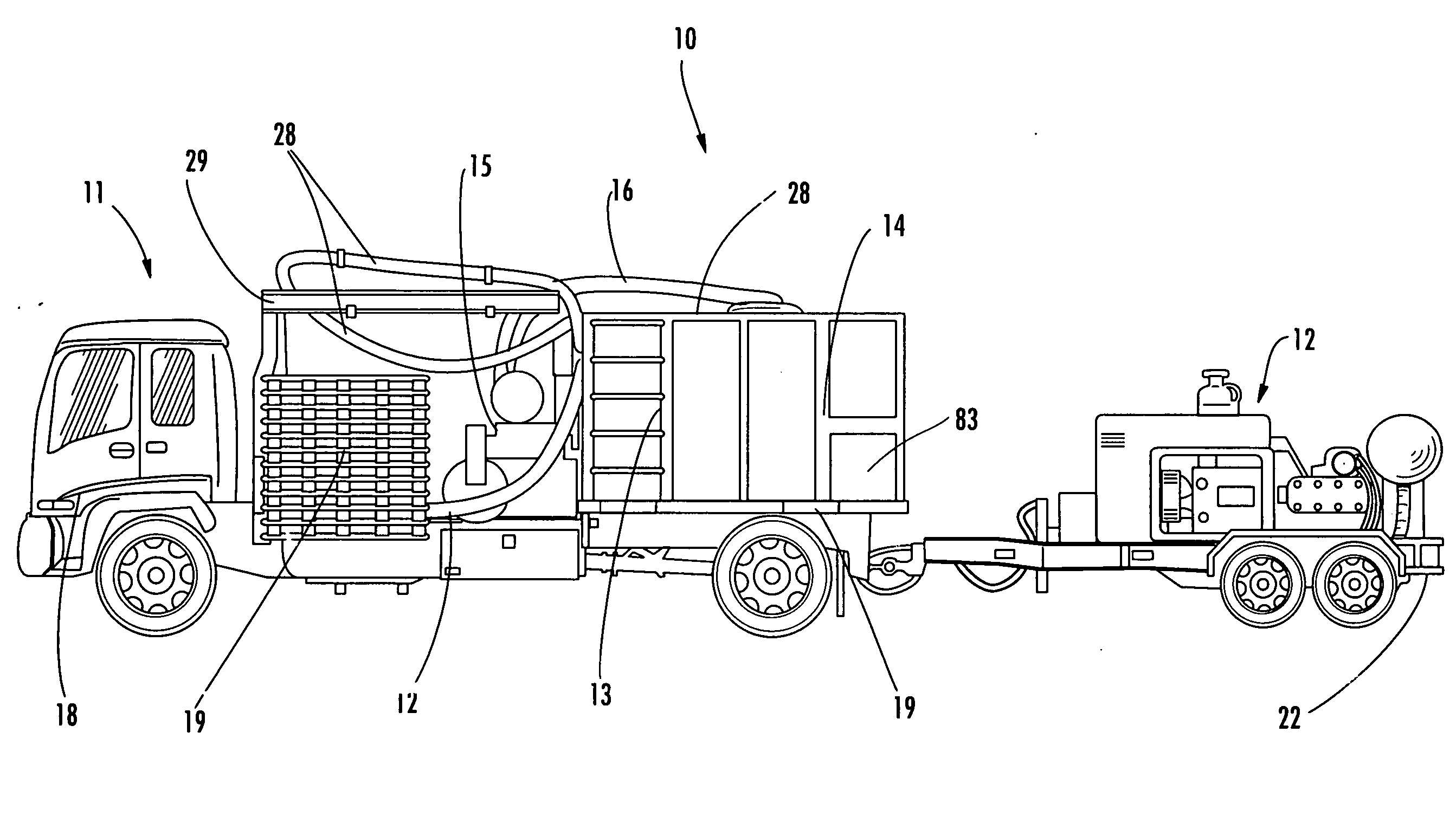
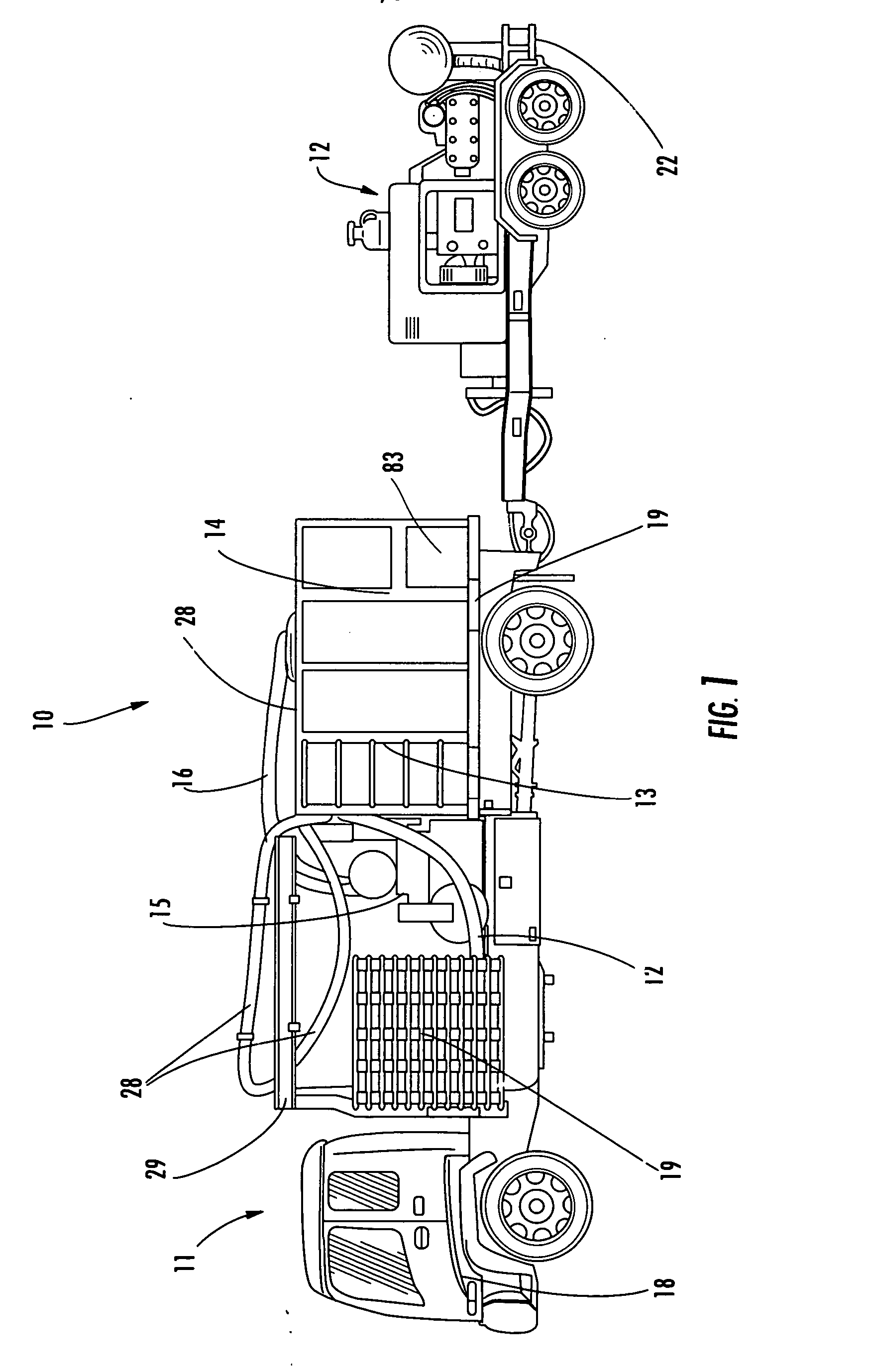
[0031] The paint removal system 10, shown in FIG. 1, includes a prime-mover truck 11 and a trailer 12. The truck has a forward cab-over 18 for the driving controls and operator. Mounted on the bed 81 of the truck is the water reservoir 13 and the sump 14 or vacuum chamber. The reservoir and sump are interconnected by a strategically positioned duct for continuous dumping of filtered wastewater when operating from a fixed position where liquid is supplied to the high pressure pump by a means other than the reservoir 13.

[0032] The sump 14 is positioned on the rear portion 82 of the bed 81. The rear portion 82 of the bed is pivotally mounted on the truck frame and hydraulicly powered to tilt in the vertical plane permitting dumping of the contents of the sump 14. The sump 14 is connected to the vacuum pump 15 by hose 16. The intake of a high power vacuum pump capable of approximately 1100 CFM (cubic feet per minute) is connected to the vacuum tank. The vacuum tank and pump are also mo...


PUM

PropertyMeasurementUnit
lengthaaaaaaaaaa
pressureaaaaaaaaaa
vacuumaaaaaaaaaa

Abstract

A transportable holding tank for containing clean water and for accepting waste from a stripe removal system. The holding tank is carried on a flatbed vehicle and requires less deck space, thus effectively increasing the cargo-carrying capacity of the vehicle compared with that available if the vehicle were carrying a conventional round or elliptical holding tank. Construction of the tank enables the holding tank to withstand a partial vacuum imposed for pumping waste into the tank. Hooks secured inside of the tank permit a bag for separating solid waste from liquid waste for easy disposal of semi dried materials.

Description

RELATED APPLICATIONS [0001] This application is a continuation-in-part of Ser. No. 10 / 884,643, filed Jul. 2, 2004 and entitled “Stripe Removal System”, the contents of which are incorporated herein in their entirety.FIELD OF THE INVENTION [0002] This invention relates to the field of high pressure water cleaning devices for highways, runways, parking decks, and other hard surfaces. PRIOR ART BACKGROUND [0003] The use of paint stripes on road surfaces is the accepted method to indicate vehicle lanes, crossing lanes, parking areas and numerous other indicators. Various pavement marking techniques are known, including the use of traffic paint, thermoplastic, epoxy paint and preformed tapes. Common pavement surfaces are asphalt and concrete. Most pavement marking systems are intended to be as durable and permanent as possible, and resistant to weathering and wear from traffic. The removal of such striping is typically required when the road is to be resurfaced or if the indication is to...

Claims


Application Information

Patent Timeline
Patent Type & Authority Applications(United States)
IPC IPC(8): B08B3/02
CPCB08B3/02E01H1/103
Inventor CROCKER, JAMES P.
Owner CROCKER JAMES P
Learn More