Liquid cooling system

Active Publication Date: 2006-08-24
MAXELL HLDG LTD
View PDF16 Cites 15 Cited by
  • Summary
  • Abstract
  • Description
  • Claims
  • Application Information

AI Technical Summary

Benefits of technology

[0012] Then, according to the present invention, accomplished by taking the drawbacks of the conventional arts mentioned above into the consideration thereof, an object thereof is to provide a liquid cooling system, enabling the small-sizing thereof, and having a driving means of a new type, to be effective for lowering the noises during when the electronic apparatus is operating; therefore, being suitable to be applied into the personal computers of the desktop type and the notebook type, and also the server, etc.
[0016] According to the present invention mentioned above, there can be obtained an effect of providing a liquid cooling system, enabling the small-size thereof, through building up a transfer mechanism for the coolant with applying a phenomenon, so-called the thermal siphon, therein, and being effective for reducing the noises which are generated during the time when the apparatus is operated; therefore, it is possible to achieve a cooling effect, with certainty, irrespective of the positions where the heat-receiving jacket and the radiator are provided.

Problems solved by technology

However, in recent years, small-sizing and high-integration on the semiconductor integrated circuit element, as being the heat-generating element, causes a problem, such as, localizing portions of generating the heat within the heat-generating element.
For this reason, under the present situation, it is not always possible to deal with such the requirement with the circulation pump of the conventional arts mentioned above.

Method used


Image

  • Liquid cooling system
  • Liquid cooling system
  • Liquid cooling system

Examples


Embodiment Construction

[0023] Hereinafter, embodiments according to the present invention will be fully explained by referring to the attached drawings.

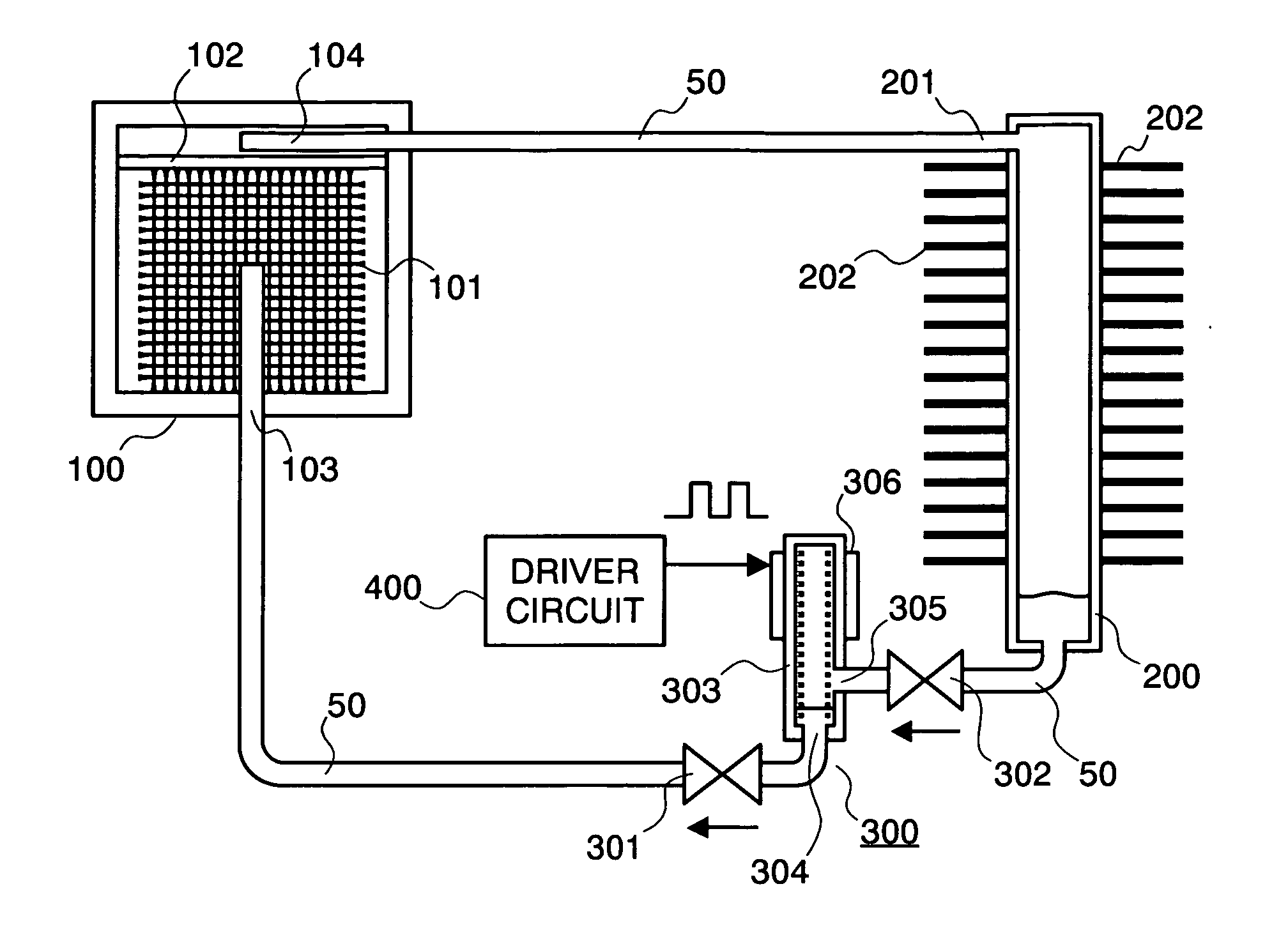
[0024] First of all, FIG. 1 attached herewith shows the entire structures of the liquid cooling system, according to one embodiment of the present invention, and basically, it comprises a heat-receiving jacket 100, a radiator 200, and a liquid driving apparatus for circulating a liquid coolant (for example, a pure water, etc.) within the liquid cooling system, wherein pipes or conduits 50, being made of a metal and so on, are connected between them, thereby building up a closed loop.

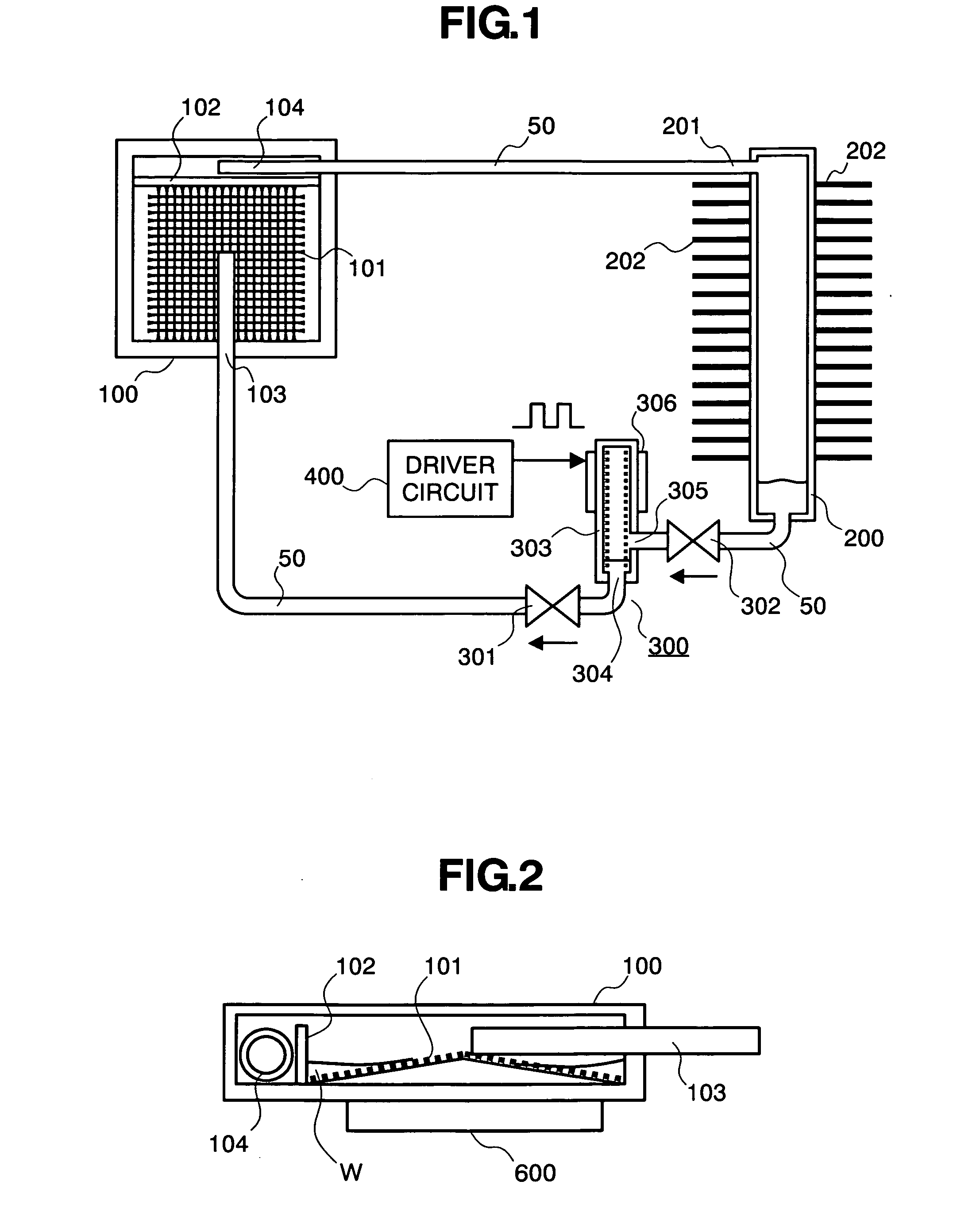
[0025] Explaining in more details thereof, the heat-receiving jacket 100 in the figure has a rectangular plate-like outer configuration, and it is made of a metal, such as, copper, aluminum, or the like, for example, being superior in the thermal or heat conductivity thereof. Internal structures of the heat-receiving jacket 100 is shown by a cross-section view thereof, in FIG...


PUM


Abstract

For providing a liquid cooling system for an electronic apparatus having a heat-generating element within a housing thereof, enabling small-sizes thereof and being effective for lowering noises when the apparatus is operated, equipped with a new type of a driving means for a liquid coolant therein, comprises a heat-receiving jacket 100 for transferring heat generated from the heat-generating element to a liquid coolant, to evaporate it, within an inside thereof; a radiator 200 for guiding the evaporated coolant supplied from the heat-receiving jacket into an inside thereof, so as to cool it to be liquefied; and a driving means 300 for applying driving force for circulating the liquid coolant, through repetition of heating and cooling upon a portion of the liquefied liquid coolant supplied from the radiator, while restricting a flow direction of the liquid coolant within an inside thereof into one direction, whereby circulating said liquid coolant within a circulation loop including the heat-receiving jacket, the radiator, and the driving means.

Description

BACKGROUND OF THE INVENTION [0001] The present invention relates to an electronic apparatus, such as, a personal computer and / or a server, etc., and in particular, it relates to a liquid cooling system, being enable to cool a semiconductor integrated circuit element mounted within an inside thereof, as being a heat-generating element, with using a liquid coolant, effectively. [0002] In general, a heat-generating element, for example, a semiconductor integrated circuit element, which generates heat within the electronic apparatus, such as, a personal computer of desk-top type or notebook type, or a server, etc., and in particular, a CPU (i.e., a central processing unit), representatively, it needs a cooling for maintaining the normal operation thereof. Conventionally, for that reason, it is general that such cooling is achieved with using a heat-transfer body, which is built up with fins called by a heat sink, to be a unit, and also a fan for sending a cooling wind upon the surface t...

Claims


Application Information

Patent Timeline
IPC IPC(8): H05K7/20
CPCF28D15/0266H01L23/427H01L2924/0002H01L2924/00
Inventor OHASHI, SHIGEO
Owner MAXELL HLDG LTD
Why Eureka
Try Eureka