

Rotor and method of manufacturing the same
a technology of rotor and manufacturing method, which is applied in the direction of electric devices, propulsion by batteries/cells, magnetic circuit shapes/forms/construction, etc., can solve the problems of not being able to disclose and how to address, so as to prevent deterioration in the strength of the rotor core, promote the spread of filler, and increase the width
- Summary
- Abstract
- Description
- Claims
- Application Information
AI Technical Summary
Benefits of technology
Problems solved by technology
Method used
Image

Examples
first embodiment
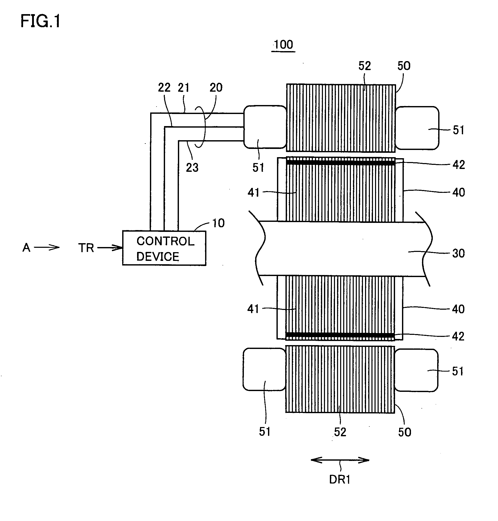
[0043]FIG. 1 is a cross-sectional view showing an example of a rotating electric machine having a rotor according to a first embodiment of the present invention. Referring to FIG. 1, rotating electric machine 100 includes a control device 10, a three-phase cable 20, a shaft 30, a rotor 40 and a stator 50.
[0044] Rotor 40 includes a rotor core 41 and a permanent magnet 42. Stator 50 includes a stator coil 51 and a stator core 52.
[0045] Control device 10 receives, from an ECU (Electrical Control Unit) provided on the outside of rotating electric machine 100, a torque command value TR to be output by rotating electric machine 100, generates motor control current MCTLI for outputting the torque designated by the received torque command value TR, and supplies the generated motor control curent MCTLI through three-phase cable 20 to stator coil 51 of stator 50.
[0046] Three-phase cable 20 connects control device 10 and stator coil 51 to each other. Three-phase cable 20 is comprised of a U...
second embodiment
[0067]FIG. 14 is a longitudinal cross-sectional view showing a magnet-inserted portion and therearound of a rotor according to a second embodiment. Referring to FIG. 14, the rotor in the present embodiment is a modification of the rotor in the first embodiment and is characterized in that a groove 41B is formed as the resin-spread promoting portion in rotor core 41.
[0068] Groove 41B is formed as shown in FIG. 14 by providing a portion that is a part of the hole for inserting a magnet therein, that is in a few of the magnetic plates constituting rotor 41, and that is different in width from the remaining portion of the hole. Thus, a separate cutting process for forming groove 41B is unnecessary.
[0069] In the present embodiment, as described above, rotor core 41 has groove 41B formed therein as the spread-promoting portion that promotes the spread of the injected resin. With this structure as well, the effect similar to that of the first embodiment can be obtained.
third embodiment
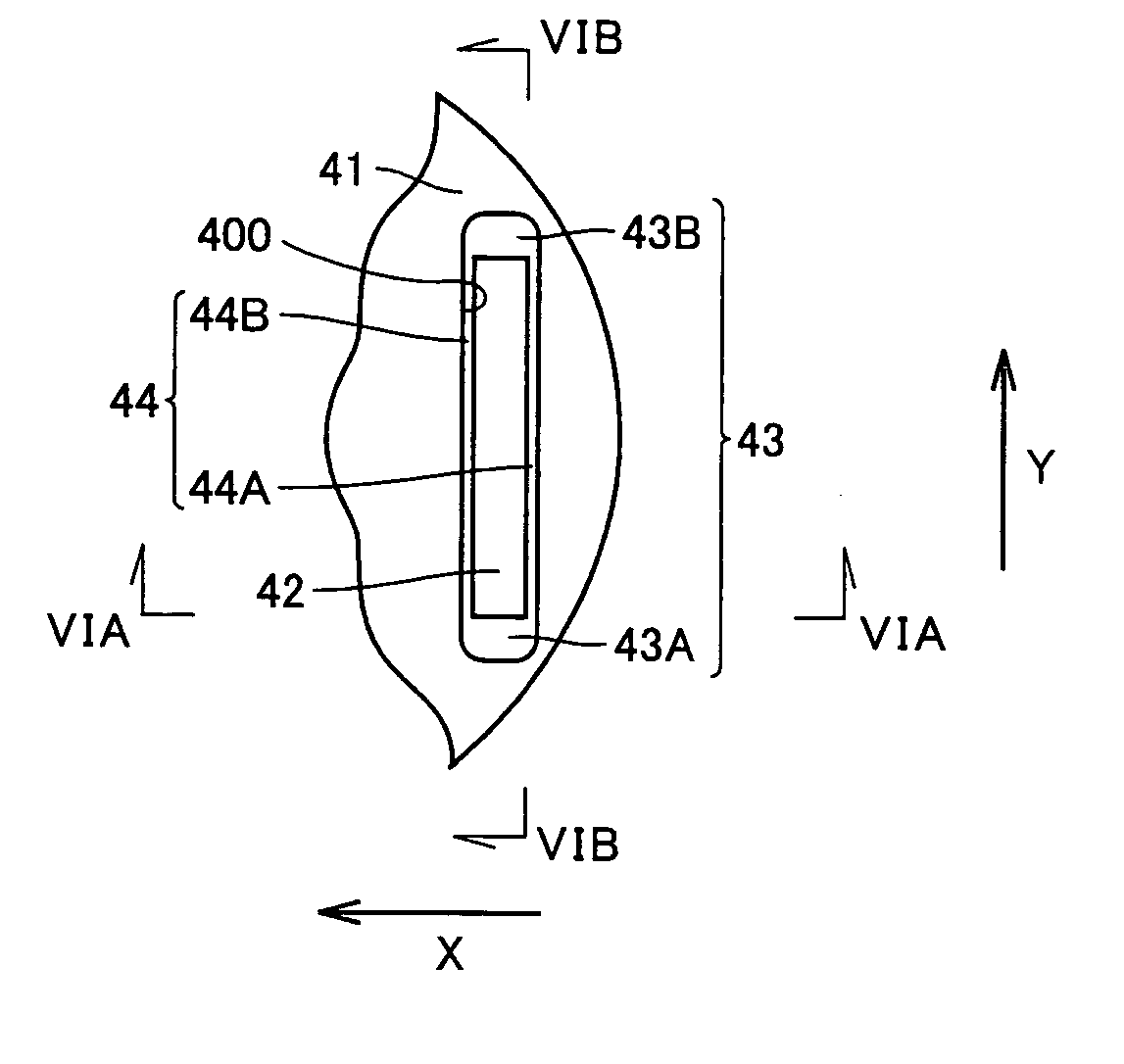
[0070]FIG. 15 is a plan view showing a magnet-inserted portion and therearound of a rotor according to a third embodiment. Referring to FIG. 15, the rotor in the present embodiment is a modification of respective rotors of the first and second embodiments and is characterized in that a chamfered portion 42J is formed on permanent magnet 42 as a resin-spread promoting portion.
[0071] As chamfered portion 42J is formed, spread of resin 45 is facilitated in the gap with a relatively small width between the side surface of permanent magnet 42 and the inner peripheral surface of the magnet-inserted hole. With this structure as well, the effect similar to that of the first and second embodiments can be obtained.
[0072]FIGS. 16A and 16B show a modification of the spread-promoting portion shown in FIG. 15. Here, FIG. 16A is a plan view of the rotor and FIG. 16B is a longitudinal cross-sectional view of the rotor (cross section along XVIB-XVIB in FIG. 16A). Referring to FIG. 16A, regarding t...
PUM
 Abstract
Description
Claims
Application Information