Method and apparatus for controlling on-vehicle generator

a technology for controlling apparatus and generator, which is applied in the direction of electric generator control, motor/generator/converter stopper, dynamo-electric converter control, etc. it can solve the problem of increasing the difference between values of detected values, increasing the difficulty of real-time detection of exciting current, and various types of control of detected exciting current in inaccurate manners. achieve the effect of rapid decay of output voltag

Active Publication Date: 2006-08-24
DENSO CORP
View PDF10 Cites 16 Cited by
  • Summary
  • Abstract
  • Description
  • Claims
  • Application Information

AI Technical Summary

Benefits of technology

[0011] The present invention has been made in consideration of the above drawbacks and provides a method and apparatus for controlling an on-vehicle generator, which are able to detect an exciting current with precision even when the output voltage of the generator shows a sharp rise due to, for example, an electric disconnection of an electric load from a power system including the generator and to make the raised output voltage decay as quickly as possible.

Problems solved by technology

The longer such a period during which the transistor is in an off state, the more difficult the exciting current detected in real time.
Therefore, in such a case, the detection of the exciting current becomes inaccurate, causing various types of control on the detected exciting current to be done in an inaccurate manner.
This decrease will thus increase a difference between values of the detected and actual exciting currents, thereby decreasing accuracy in detecting the exciting current.
As a result, the detected exciting current will not lead to an accurate calculation of a torque to be generated, with the result that the engine cannot be controlled properly.
However, the above minimum-duty technique is confronted with another drawback.
That is, since the vehicle control generation apparatus is obliged to maintain the exciting current at a minimum duty or more at any time, the output voltage of the vehicle generator will increase to invite an excessive voltage state when being rotated at a high speed.

Method used


Image

  • Method and apparatus for controlling on-vehicle generator
  • Method and apparatus for controlling on-vehicle generator
  • Method and apparatus for controlling on-vehicle generator

Examples


Embodiment Construction

[0028] An embodiment of an on-vehicle generation control apparatus according to the present invention will now be described with reference to the accompanying drawings.

[0029] Referring to FIGS. 1-5, the on-vehicle generation control apparatus according to the embodiment will now be described.

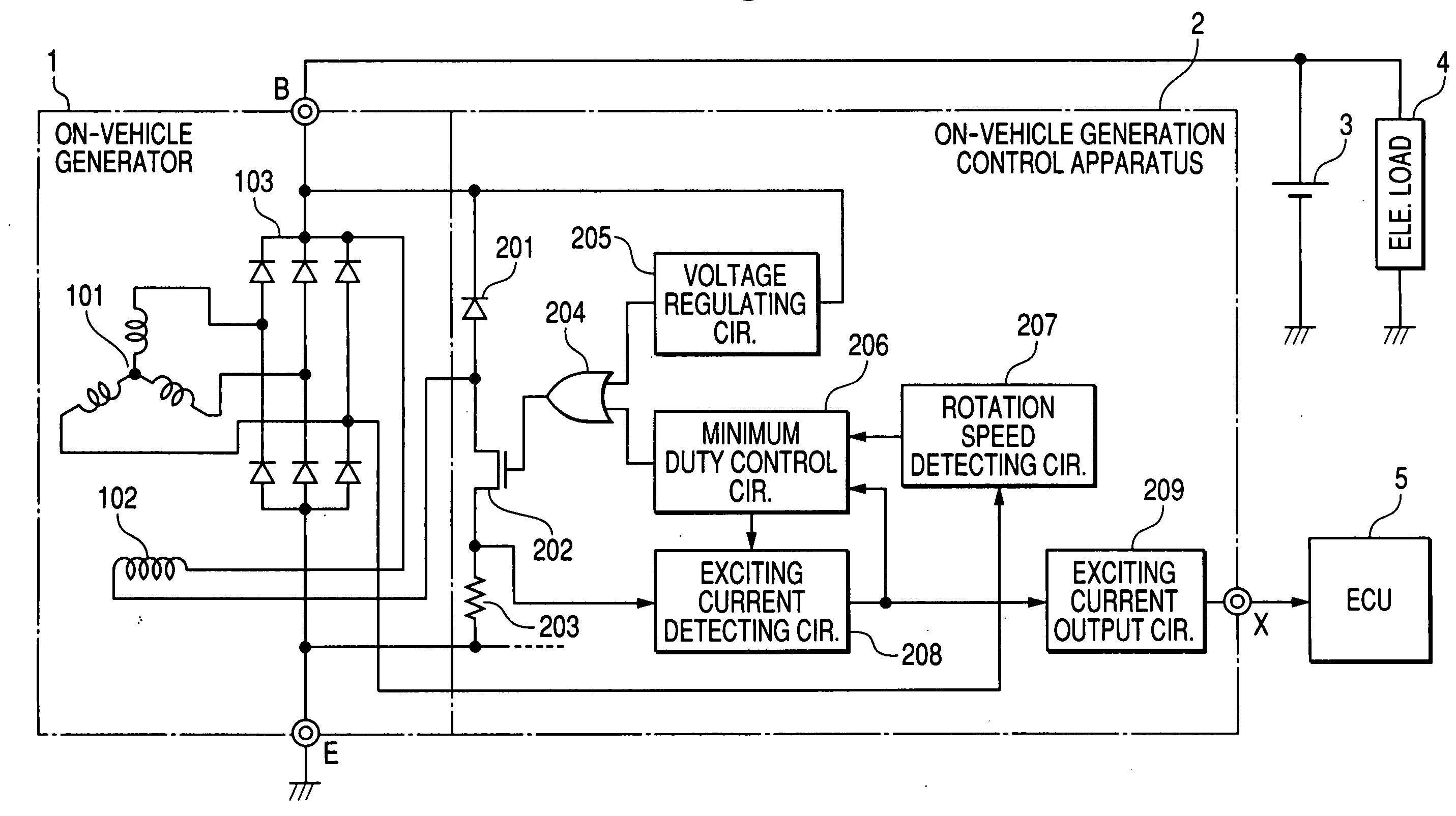
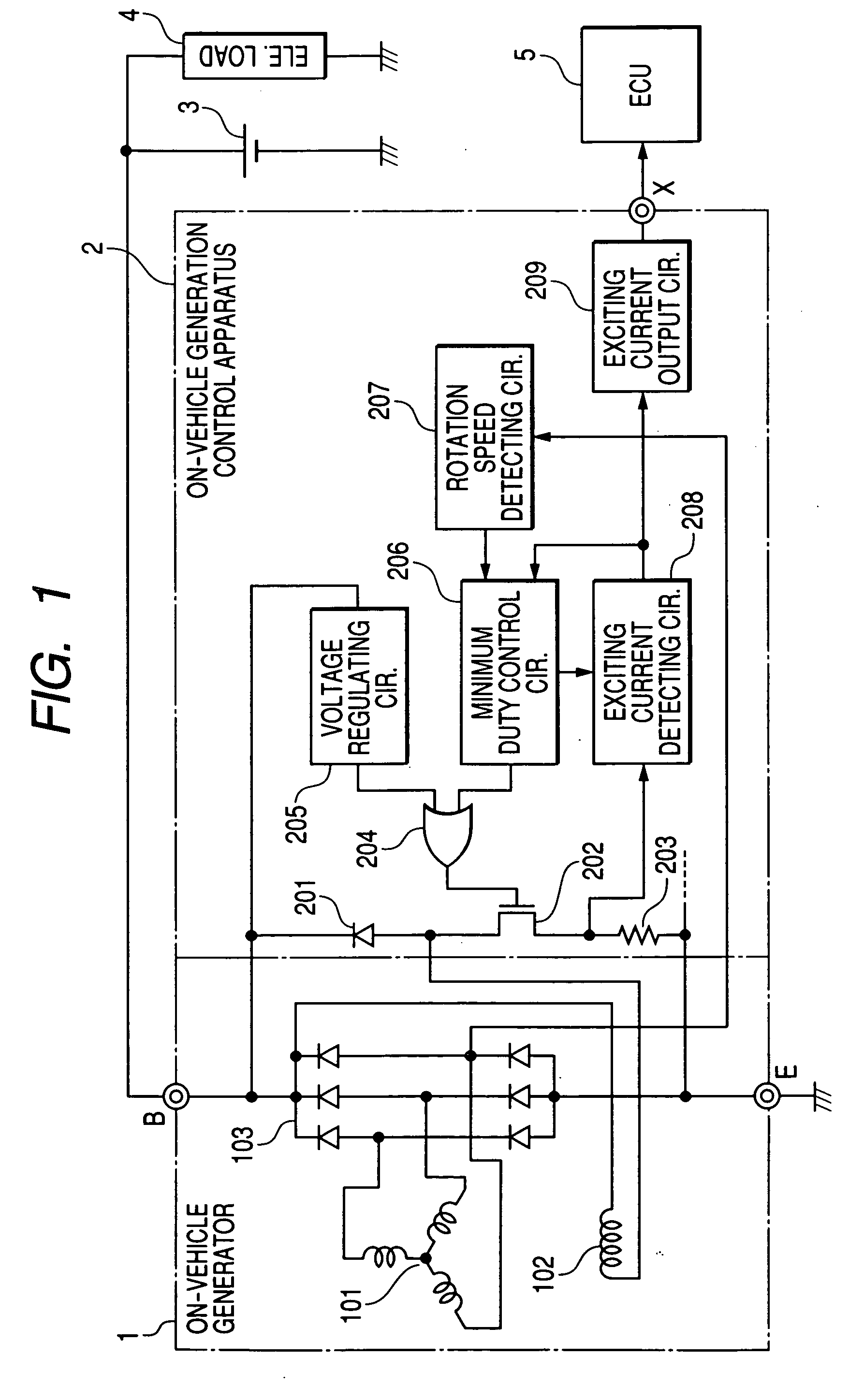
[0030] FIG, 1 shows the arrangement of a generator 1 and a generation control apparatus 2 both adopted by the embodiment, in which both of the generator 1 and the generation control apparatus 2 are mounted on a vehicle or are to be mounted on a vehicle. This arrangement on the vehicle involves a battery 3, an electric load(s) 4, and an ECU (electric control unit) 5 communicably connected to an engine mounted on the vehicle. In the embodiment, the electric load 4 is described as being an electric component which requires a large amount of power, such as an air conditioner.

[0031] The generation control apparatus 2 is provided such that a voltage at an output terminal (B terminal) of the generat...


PUM


Abstract

An apparatus for controlling an on-vehicle generator is provided. The apparatus comprises a switching element, current detecting unit, setting unit and driving unit. The switching unit turns on/off an exciting current to an exciting winding of the generator, the switching element being driven responsively to a driving signal having an adjustable duty ratio. The setting unit sets the duty ratio based on (i) a difference between an output voltage of the generator and a target voltage value and (ii) a condition in which an electric load is disconnected from the generator, wherein the duty ratio is allowed to lower than a minimum value of the duty ratio depending on a generated state of the generator. The minimum value allows the exciting current to flow at a lower limit detectable by the current detecting unit, The driving unit drives the switching element based on the driving signal.

Description

CROSS REFERENCE TO RELATED APPLICATION [0001] The present application is based on and claims priority from Japanese Patent Application No. 2005-044185 filed on Feb. 21 2005, the disclosure of which is incorporated herein by reference. BACKGROUND OF THE INVENTION [0002] 1. Technical Field of the Invention [0003] The present invention relates to an apparatus for controlling the drive of a generator mounted on a vehicle in order to regulate an output voltage of the generator, and in particular, to the apparatus in which control is made on an exciting current to flow through an exciting winding of the generator. [0004] 2. Related Art [0005] Various types of apparatuses for controlling the drive of on-vehicle generators have been known. One type of such control apparatus is proposed by Japanese Patent Laid-open (unexamined) Publication No. 2003-284257 and U.S. Pat. No. 6,900,618 B2. According to these publications, the control apparatus detects an excitation current and the number of eng...

Claims


Application Information

Patent Timeline
Patent Type & Authority Applications(United States)
IPC IPC(8): H02H7/06H02P9/00H02P11/00
CPCH02J7/245H02P9/14Y02T10/92H02J7/2434
Inventor YAMAMOTO, TAKAAKIMAEHARA, FUYUKI
Owner DENSO CORP
Why Eureka
Try Eureka