Method and apparatus for cooling gas turbine fuel nozzles

a gas turbine and fuel nozzle technology, applied in the direction of machines/engines, lighting and heating apparatus, combustion types, etc., can solve the problems of high nox emissions, premixed combustion can typically be sustained, flame temperature is still too hot for conventional combustor components to withstand without cooling, etc., to prevent thermal distress

Inactive Publication Date: 2006-08-31
GENERAL ELECTRIC CO
View PDF11 Cites 67 Cited by
  • Summary
  • Abstract
  • Description
  • Claims
  • Application Information

AI Technical Summary

Benefits of technology

[0010] In accordance with one embodiment of the present invention, there is provided a method of preventing thermal distress in a gas fuel nozzle used in a gas turbine having a compressor, a combustor, and a turbine. The method includes: disposing an impingement baffle plate upstream of diffusion orifices defining a nozzle tip, the baffle plate having an array of small orifices; and creating jets of cooling fluid impinging on the nozzle tip via the impingement baffle plate when at least one of fuel and air flow through the array of small orifices.
[0011] In another embodiment, a method for cooling a fuel nozzle tip is disclosed. The method includes: providing a gas fuel nozzle including an outer peripheral wall; an air flow passage defined within the outer wall and extending at least part circumferentially thereof; and a central gas fuel flow passage; securing a nozzle tip to the outer peripheral wall at a distal end thereof to substantially block the central gas flow passage, the nozzle tip including diffusion orifices defined about a periphery thereof; and disposing an impingement baffle plate upstream of diffusion orifices defining the nozzle tip, the baffle plate having an array of small orifices creating jets of fluid impinging on a back side of the nozzle tip. The cooling of the nozzle tip is accomplished with the same fluid flowing through the impingement baffle plate and the diffusion orifices eliminating an additional flow path to the nozzle tip.

Problems solved by technology

), the high temperatures of diffusion combustion result in relatively high NOx emissions.
Although lean premixed combustion is cooler than diffusion combustion, the flame temperature is still too hot for conventional combustor components to withstand without cooling.
Premixed combustion can typically be sustained only at moderate or high turbine loads, as the lighter load conditions result in premixed mixtures too lean to burn.
The first method is not very effective at cooling the tip and is risky during periods when there is neither flow of fuel nor air through the diffusion tip, such as during fuel transfer transients.
The latter method is effective at cooling the tip, but is costly and difficult due to the requirement of an additional fluid path for compressor discharge air to pass through the nozzle to the diffusion tip.
This difficulty is particularly acute for smaller gas turbines where the available space for parallel fluid passages in the nozzle tip is very limited.

Method used


Image

  • Method and apparatus for cooling gas turbine fuel nozzles
  • Method and apparatus for cooling gas turbine fuel nozzles
  • Method and apparatus for cooling gas turbine fuel nozzles

Examples


Embodiment Construction

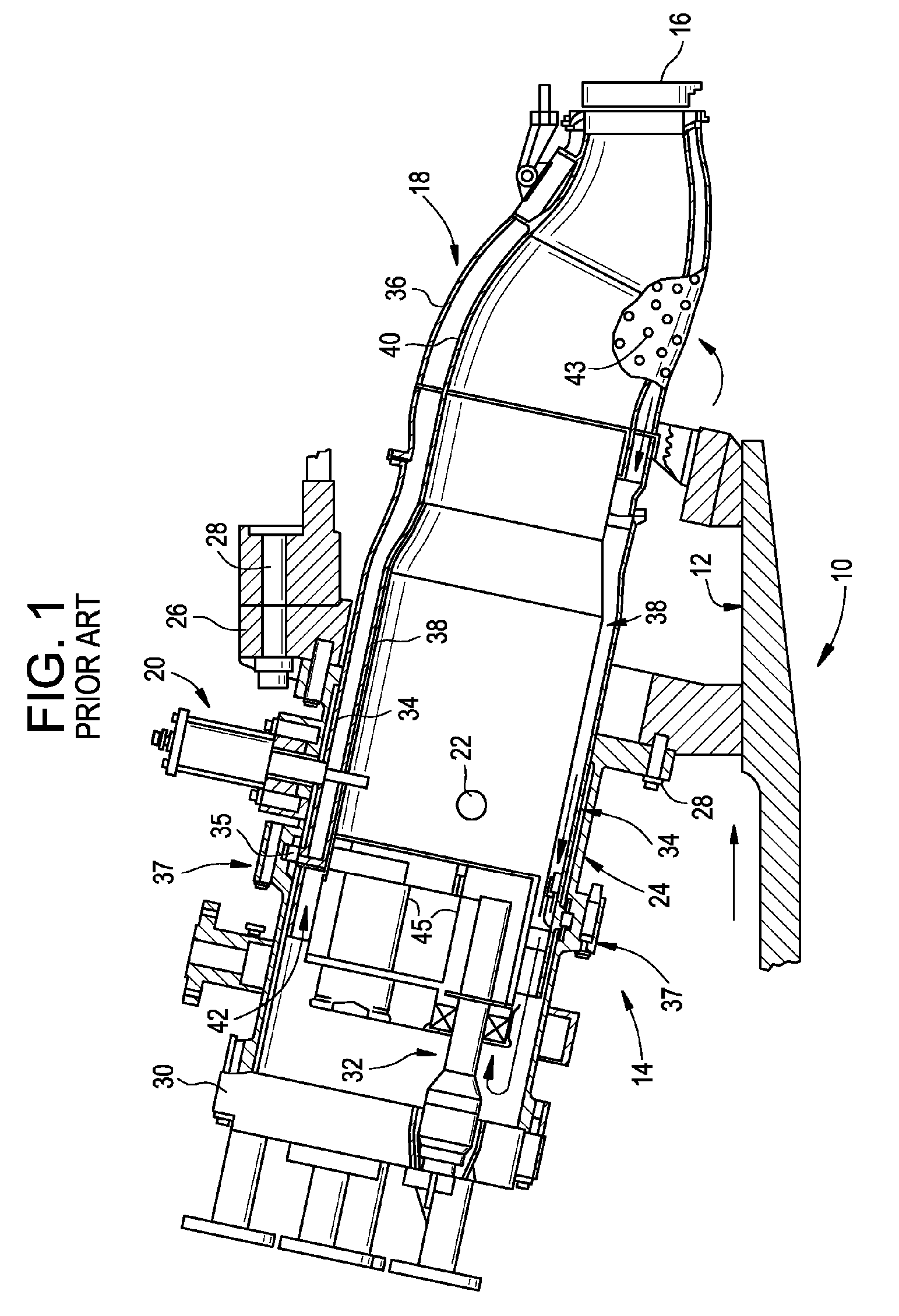
[0021] Referring to FIG. 1, a gas turbine 10 (partially shown) includes a compressor 12 (also partially shown), a plurality of combustors 14 (one shown), and a turbine section represented here by a single blade 16. Although not specifically shown, the turbine is drivingly connected to the compressor 12 along a common axis. The compressor 12 pressurizes inlet air which is then reverse flowed to the combustor 14 where it is used to cool the combustor and to provide air to the combustion process.

[0022] As noted above, a plurality of combustors 14 are located in an annular array about the axis of the gas turbine. A double-walled transition duct 18 connects the outlet end of each combustor with the inlet end of the turbine to deliver the hot products of combustion to the turbine. Ignition is achieved in the various combustors 14 by means of sparkplug 20 in conjunction with crossfire tubes 22 (one shown) in the usual manner.

[0023] Each combustor 14 includes a substantially cylindrical c...


PUM


Abstract

A method and apparatus for a nozzle of a gas turbine engine is disclosed that facilitates extending a useful life of the nozzle. The method and apparatus include an impingement baffle plate disposed at a back side of a diffusion tip of the nozzle. The method and apparatus includes the impingement baffle plate formed with an array of orifices creating jets for fuel or purge air to impinge on the diffusion tip. In this manner, cooling via convection through diffusion orifices in the diffusion tip is preserved, and cooling is made more robust.

Description

BACKGROUND OF THE INVENTION [0001] This invention relates to gas turbine combustion systems and, specifically, to a new gaseous fuel nozzle tip design which is intended to provide impingement cooling to a back side thereof in addition to cooling with fluid flow through diffusion orifices of the nozzle tip. [0002] A gas turbine combustor is essentially a device used for mixing fuel and air, and burning the resulting mixture. Typically, a heavy duty gas turbine compressor pressurizes inlet air which is then turned in direction or reverse flowed to the combustor where it is used to cool the combustor and also to provide air to the combustion process. The assignee of this invention utilizes multiple combustion chamber assemblies in its heavy duty gas turbines to achieve reliable and efficient turbine operation. Each combustion chamber assembly typically comprises a cylindrical combustor liner, a fuel injection system, and a transition piece that guides the flow of the hot gas from the c...

Claims


Application Information

Patent Timeline
Patent Type & Authority Applications(United States)
IPC IPC(8): F02C7/22
CPCF23D14/78F23R3/283F23R2900/03044F23D14/48
Inventor WIDENER, STANLEY KEVINJOHNSON, THOMAS EDWARD
Owner GENERAL ELECTRIC CO
Why Eureka
Try Eureka