Manufacturing method for pixilated crystal

a manufacturing method and crystal technology, applied in the field of improved apparatus and methods for shaping materials, can solve the problems of brittle or weak materials, dust, and the deformation of optical signals obtained from optical elements, and achieve the effect of improving the spatial resolution of scintillators

Inactive Publication Date: 2006-08-31
JUNI JACK E
View PDF6 Cites 26 Cited by
  • Summary
  • Abstract
  • Description
  • Claims
  • Application Information

AI Technical Summary

Benefits of technology

[0011] Embodiments of the present invention can be used to enhance the spatial resolution of a scintillator by forming a plurality of grooves within a surface of the scintillator. The grooves may be disposed so as to form a grid pattern over a surface of the scintillator. The grid pattern may be rectangular, or other geometry. The groo

Problems solved by technology

Edge reflections from an optical element can degrade positional accuracy of optical signals obtained from the optical element.
However, this can lead to fracture of brittle or weak materials, produces dust, and can add significant time and expense.
When cutting glass, there is a high risk of fracture

Method used


Image

  • Manufacturing method for pixilated crystal
  • Manufacturing method for pixilated crystal
  • Manufacturing method for pixilated crystal

Examples


Embodiment Construction

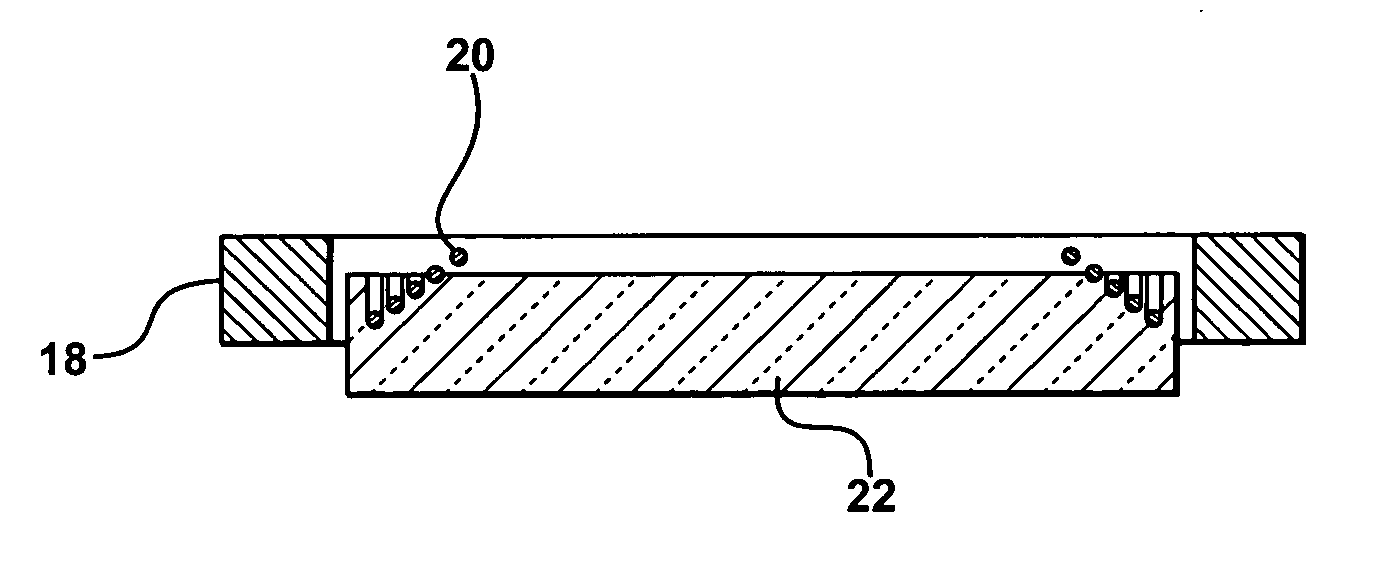
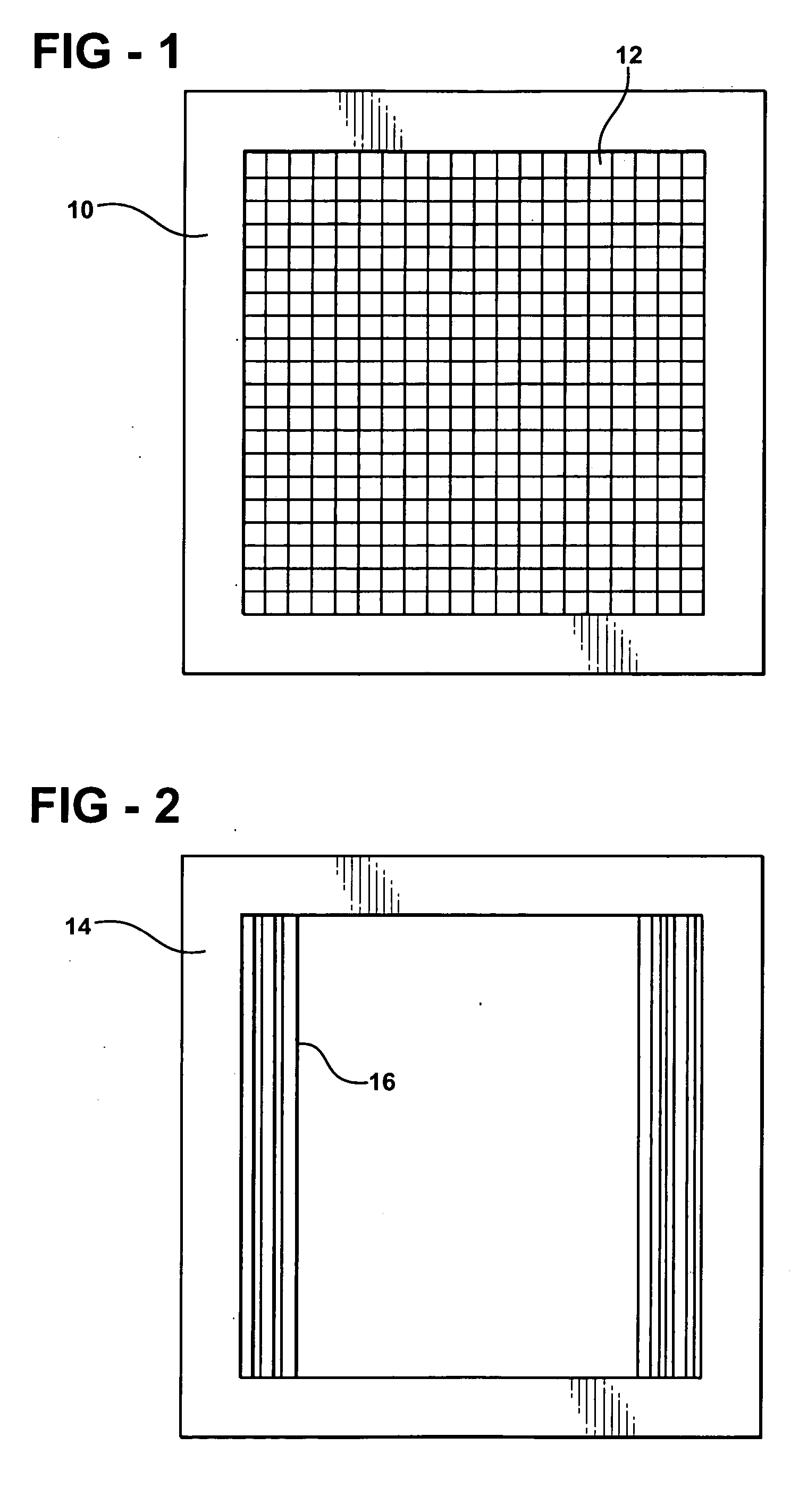
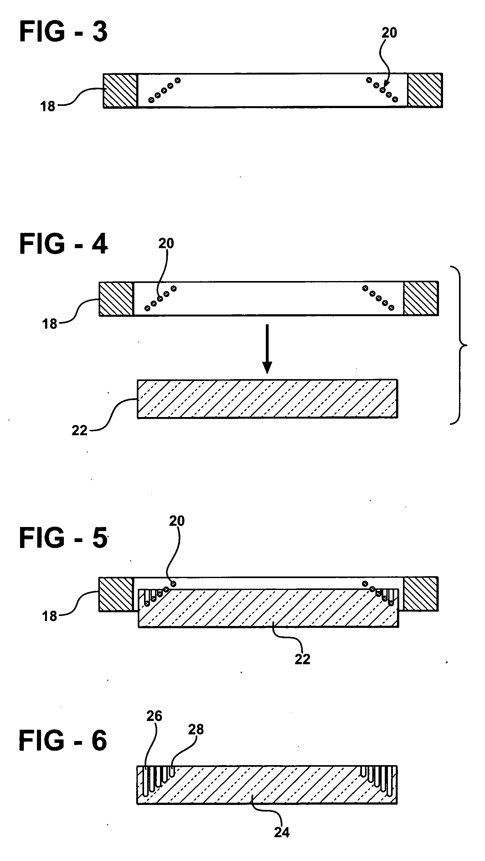
[0018] There are many reasons to modify the surface shape of a material. In the case of scintillators, internal edge reflections degrade the positional accuracy of detected scintillation light. This is described in more detail in my co-pending application, “Edge effects treatment for crystals”, U.S. patent application Ser. No. 10 / 993,012, filed Nov. 19, 2004. In this context, positional accuracy refers to the spatial relationship between the detected scintillation photons and actual scintillation events, and hence to the distribution of ionizing radiation incitement on the scintillator. Edge reflections allow scintillation light to take multiple paths out of the scintillator, namely a direct exit and internally reflected from an edge. Positional accuracy can be improved by a number of approaches, including dividing a single scintillator into multiple material segments, or by forming grooves in the surface of the scintillator. In particular, grooves formed in a peripheral region of t...


PUM


Abstract

Apparatus and methods for shaping a surface of a material are described. An example method comprises providing one or more shaping elements, softening the material, and urging the one or more shaping elements against the material so as to form one or more grooves in the material. The configuration of shaping elements can be adjusted to provide a desired pattern of grooves in the surface. The method can be applied to inorganic crystals in a high temperature plastic state, avoiding the problems associated with conventional sawing techniques.

Description

REFERENCE TO RELATED APPLICATION [0001] This application claims priority of U.S. Provisional Patent Application Ser. No. 60 / 629,410, filed Nov. 19, 2004, the entire content of which is incorporated herein by reference.FIELD OF THE INVENTION [0002] The invention relates to improved apparatus and methods for shaping a material, for example for forming grooves in a surface of a scintillation crystal. BACKGROUND OF THE INVENTION [0003] Edge reflections from an optical element can degrade positional accuracy of optical signals obtained from the optical element. One example is the scintillator crystal, where the position of light emission from a face is used in medical imaging. A scintillation material, or scintillator, produces light in response to incident radiation, typically ionizing radiation such as gamma rays or x-rays. Such a material can be a crystal such as thallium-doped sodium iodide, NaI(Tl), or a non-crystalline material such as a plastic. Scintillators are described in more...

Claims


Application Information

Patent Timeline
IPC IPC(8): B29D11/00
CPCG01T1/202G01T1/203
Inventor JUNI, JACK E.
Owner JUNI JACK E
Why Eureka
Try Eureka