Manufacturing method of head gimbal assembly with solder fillet and head gimbal assembly

Inactive Publication Date: 2006-08-31
WESTERN DIGITAL TECH INC
View PDF5 Cites 18 Cited by
  • Summary
  • Abstract
  • Description
  • Claims
  • Application Information

AI Technical Summary

Benefits of technology

[0018] According to the present invention, a method of manufacturing the HGA can be provided by reflowing the solder mass deposited on the slider pad of the head/slider and thereby making a good soldered connection

Problems solved by technology

The solder ball connection technique is, however, associated with problems of improper connection unique thereto.
Possible problems include: the molten solder attracted one-sidedly to either one of the pads during reflow of the solder ball 315 using la

Method used


Image

  • Manufacturing method of head gimbal assembly with solder fillet and head gimbal assembly
  • Manufacturing method of head gimbal assembly with solder fillet and head gimbal assembly
  • Manufacturing method of head gimbal assembly with solder fillet and head gimbal assembly

Examples


Embodiment Construction

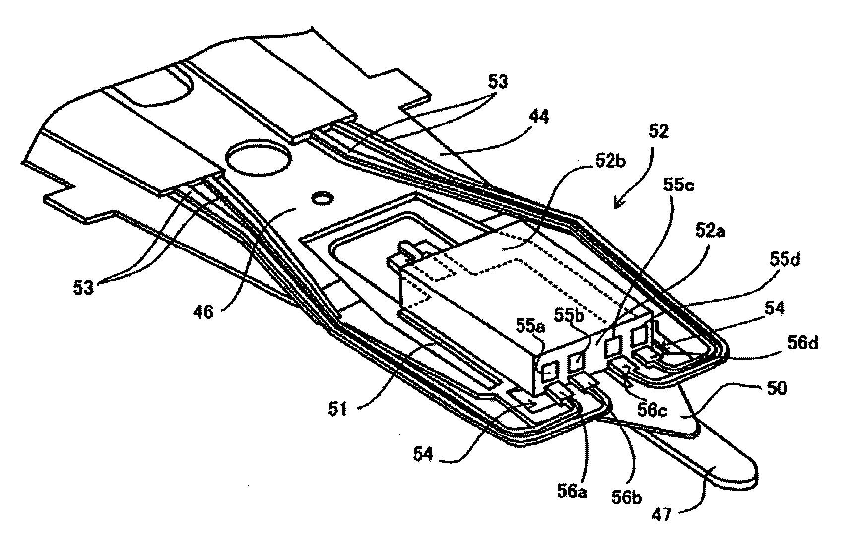
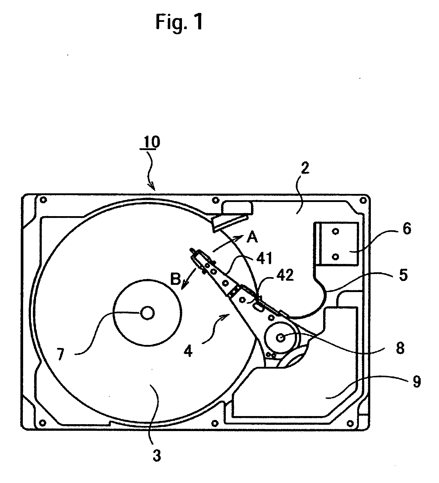
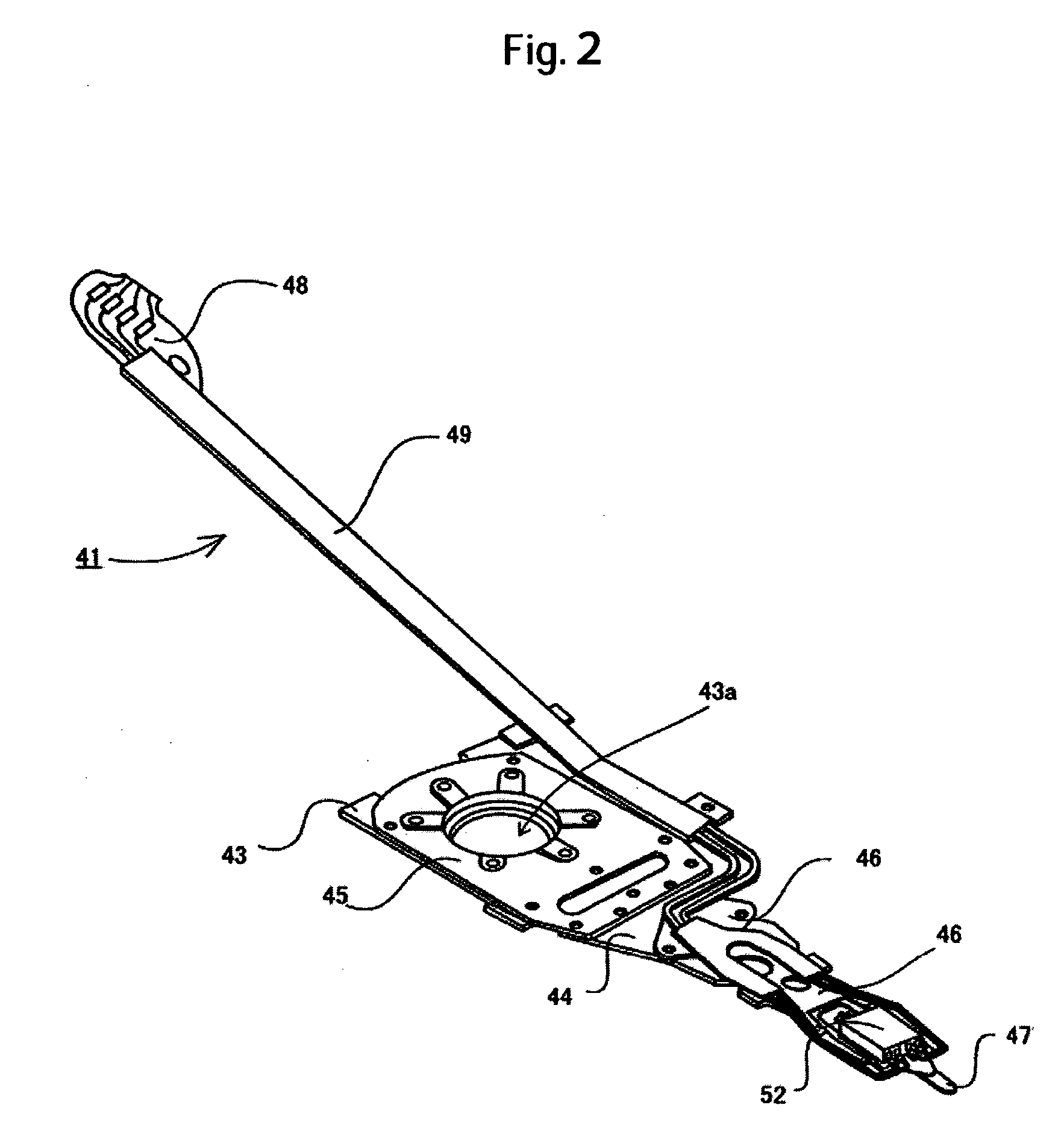
[0033] An exemplary embodiment of the present invention will be described with reference to the accompanying drawings. Throughout all accompanying drawings, like parts are identified by the same reference numerals. FIG. 1 is a plan view showing the construction of a magnetic disk drive. FIG. 2 is a perspective view showing a general construction of an HGA. FIG. 3 is a partly enlarged view showing a head / slider portion of the HGA shown in FIG. 2. Referring to FIG. 1, a magnetic disk drive 10 includes a magnetic disk 3, a head stack assembly 4, a flexible cable 5, and a terminal 6, all mounted on a base 2. The terminal 6 is for connecting the flexible cable 5 to an external circuit board. The magnetic disk 3 is screwed to a rotor portion of a spindle motor (not shown) disposed on the base 2, designed to be rotatably driven about a spindle shaft 7.

[0034] The head stack assembly 4 includes an HGA 41 and an actuator assembly 42. The HGA 41 is constructed as shown, for example, in FIGS. ...


PUM

PropertyMeasurementUnit
Temperatureaaaaaaaaaa
Fractionaaaaaaaaaa
Widthaaaaaaaaaa

Abstract

Embodiments of the invention relate to making reconnection when a soldered connection fails in a head/slider used in a magnetic disk drive. In one embodiment, a solder mass deposited on a slider pad of a head/slider is separated from a lead pad and a solder ball connection is yet to be made between the slider pad and the lead pad. A shaping tip is heated to a temperature near a melting point of a solder. The shaping tip is moved in parallel with a surface of the slider pad toward the side of the lead pad to soften the solder mass. The solder mass is thereafter irradiated with a laser beam so as to form a solder fillet, thereby making a soldered connection between the lead pad and the slider pad.

Description

CROSS-REFERENCES TO RELATED APPLICATIONS [0001] This application claims priority from Japanese Patent Application No. JP2005-050641, filed Feb. 25, 2005, the entire disclosure of which is incorporated herein by reference. BACKGROUND OF THE INVENTION [0002] The present invention relates to a technique for connecting a slider pad and a lead pad of a head gimbal assembly included in a magnetic disk drive. More particularly, the present invention relates to a technique for making a soldered connection between the slider pad and the lead pad by re-irradiating a solder mass with a laser beam, the solder mass being deposited on the slider pad as a result of a solder ball being irradiated with the laser beam. [0003] In the magnetic disk drive, a head formed in a slider (a structure integrating a head with a slider will hereinafter be referred to as a head / slider) flies above a surface of a magnetic disk with an extremely small gap from the surface and reads data from, or writes data to, the...

Claims


Application Information

Patent Timeline
IPC IPC(8): G11B5/60
CPCG11B5/4853H05K3/3442H05K3/3494H05K2201/10727H05K2203/0195H05K2203/041Y10T29/49211H05K2203/107H01L2224/742H01L2924/01327H05K2203/043Y10T29/4903H01L2924/00Y02P70/50
Inventor SATOH, TAKUYAYOSHIDA, TATSUSHITSUCHIYA, TATSUMIUEMATSU, YOSHIO
Owner WESTERN DIGITAL TECH INC
Why Eureka
Try Eureka