Exhaust gas purifying apparatus for internal combustion engine

a technology for exhaust gas purification and internal combustion engines, which is applied in the direction of machines/engines, electrical control, separation processes, etc., can solve the problems of inability to detect the leakage amount of particulates due to the failure, the filtering capability of the dpf will be deteriorated, and the failure cannot be detected. , to achieve the effect of accurate detection of the failure state of the dpf and simple configuration

Inactive Publication Date: 2006-09-07
HONDA MOTOR CO LTD
View PDF1 Cites 33 Cited by
  • Summary
  • Abstract
  • Description
  • Claims
  • Application Information

AI Technical Summary

Benefits of technology

[0008] The present invention is made contemplating the above-described points. An object of the present invention is to provide an exhaust gas purifying apparatus which can accurately detect a state of a failure of the DPF with a comparatively simple configuration.

Problems solved by technology

If a failure such as a crack or a hole occurs in the filter element of the DPF, the filtering capability of the DPF will be deteriorated and the emission amount of particulates will increase.
According to the technique shown in Japanese Patent Laid-open No. 2004-308454, a leak amount of particulates due to the failure cannot be detected.
Therefore, it is difficult to satisfy the demand of detecting a failure before the leak amount of particulates exceeds a predetermined amount due to reduction in the particulate trapping capacity of the DPF.
Further, according to the technique shown in Japanese Patent Laid-open No. 2004-308454, complicated calculations are necessary for monitoring and analyzing the pulsation amplitude of the exhaust pressure.
However, development of such sensor has not yet been completed.

Method used


Image

  • Exhaust gas purifying apparatus for internal combustion engine
  • Exhaust gas purifying apparatus for internal combustion engine
  • Exhaust gas purifying apparatus for internal combustion engine

Examples


first embodiment

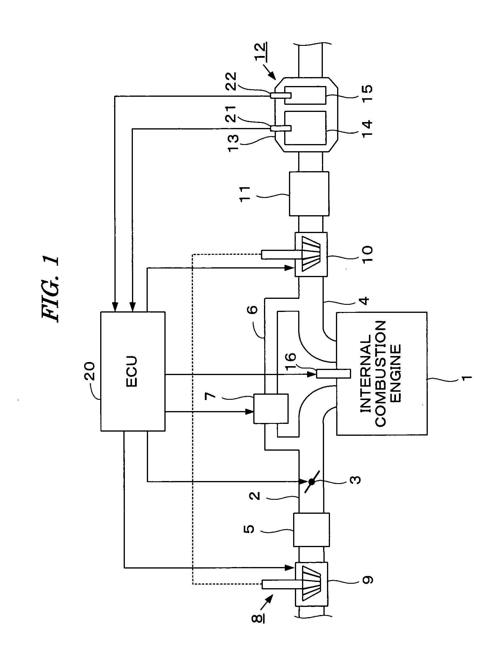
[0031]FIG. 1 is a schematic diagram showing a configuration of an internal combustion engine having an exhaust gas purifying apparatus and a control system therefor according to a first embodiment of the present invention. The internal combustion engine 1 (hereinafter referred to as “engine”) is a diesel engine in which fuel is directly injected into cylinders. Each cylinder is provided with a fuel injection valve 16. The fuel injection valve 16 is electrically connected to an electronic control unit (hereinafter referred to as “ECU”) 20. The ECU 20 controls a valve opening period and a valve opening timing of the fuel injection valve 16.

[0032] The engine 1 has an intake pipe 2, an exhaust pipe 4, and a turbocharger 8. The turbocharger 8 includes a turbine 10 and a compressor 9. The turbine 10 is driven by the kinetic energy of exhaust gases. The compressor 9, which is rotationally driven by the turbine 10, compresses intake air of the engine 1.

[0033] The turbine 10 has a pluralit...

second embodiment

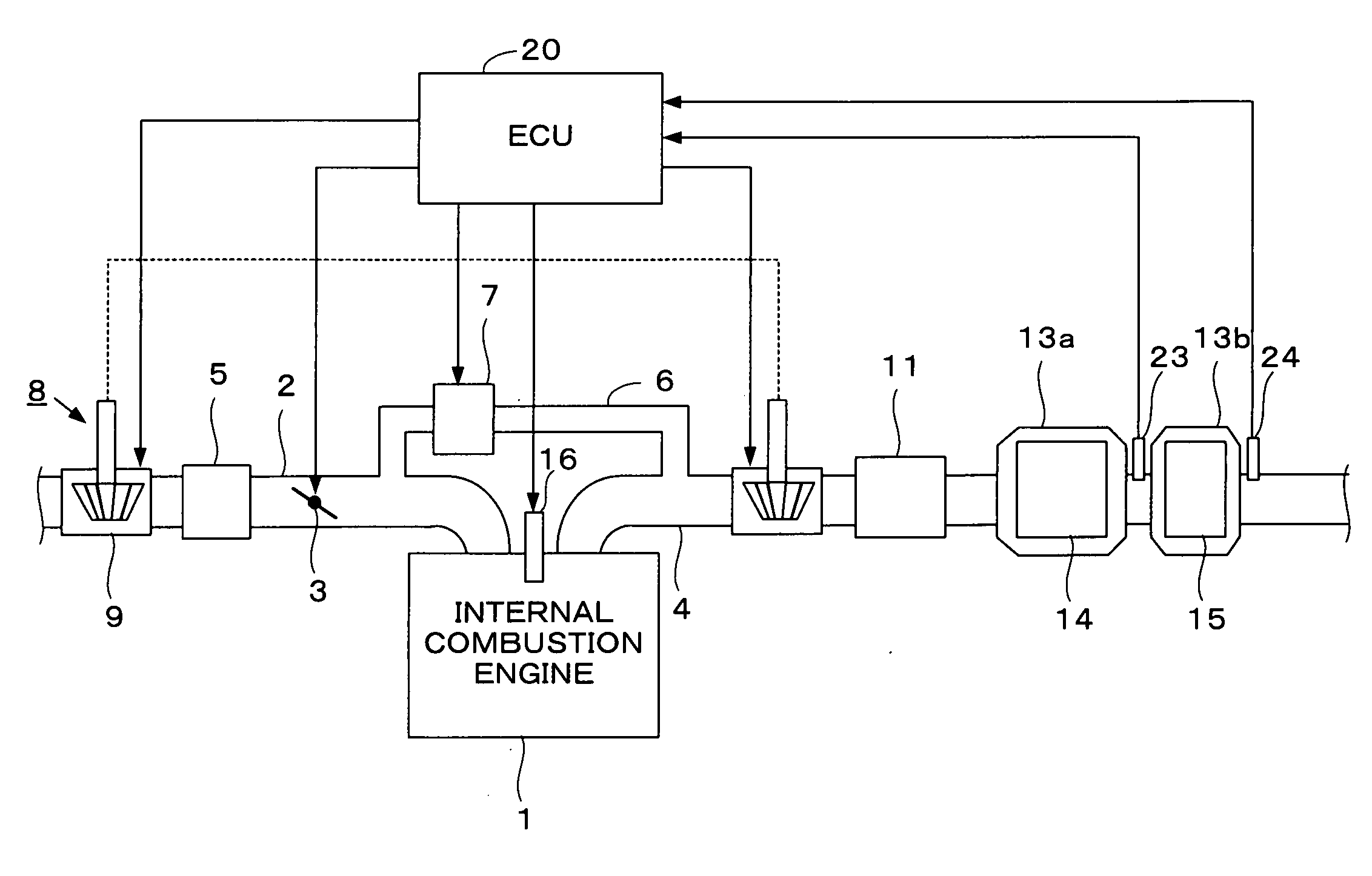
[0066]FIG. 5 is a schematic diagram showing a configuration of an internal combustion engine having an exhaust gas purifying apparatus, and a control system therefore, according to a second embodiment of the present invention. In this embodiment, the main DPF 14 and the sub DPF 15 are contained respectively in containers 13a and 13b, and pressure sensors 23 and 24 are provided respectively on the upstream side and the downstream side of the sub DPF 15. The detection signals of pressure sensors 23 and 24 are supplied to the ECU 20. Except this point, the configuration is the same as that of the first embodiment shown in FIG. 1.

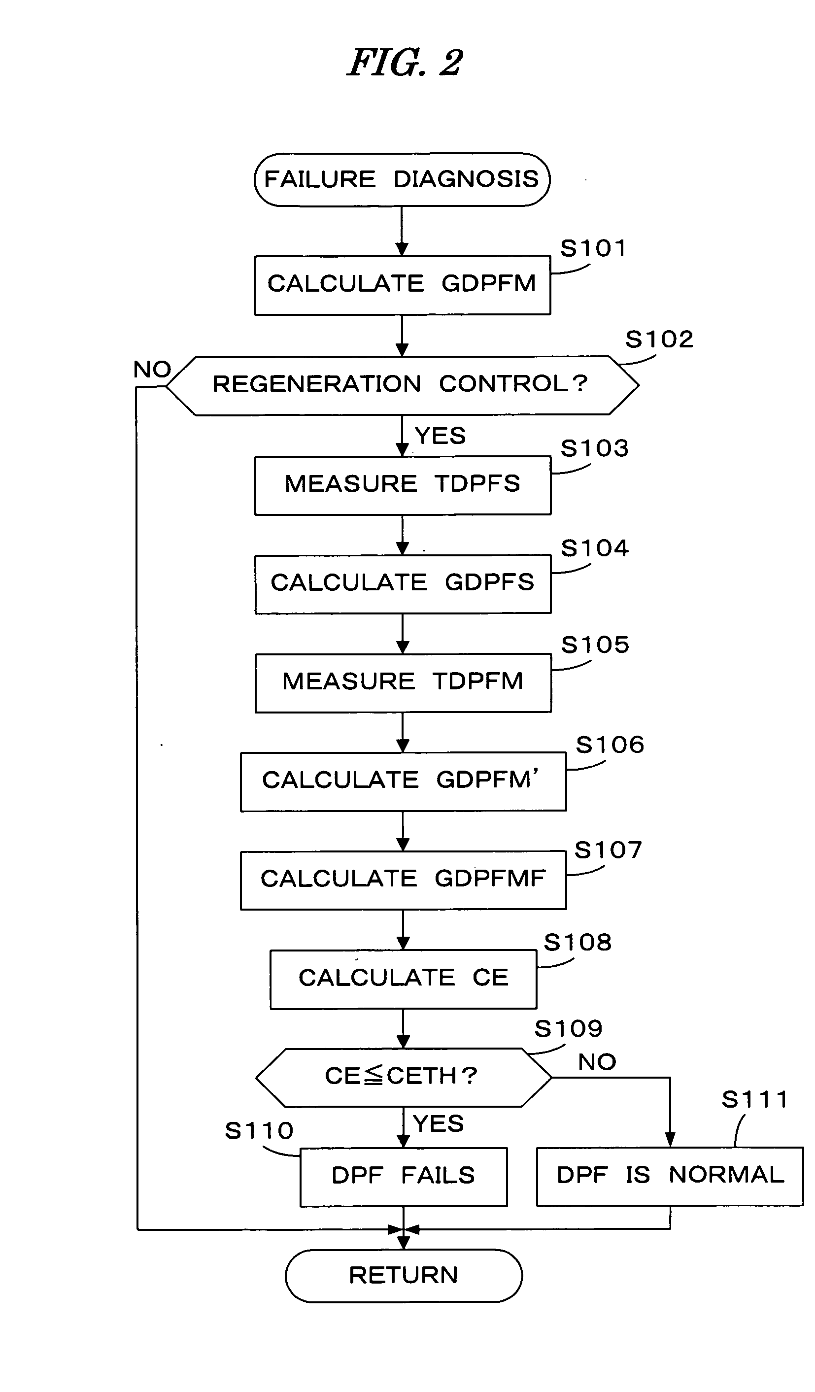
[0067]FIG. 6 is a flowchart showing a method of the failure diagnosis in this embodiment. In step S201, the main DPF accumulation amount GDPFM is calculated similarly in step S101 of FIG. 2. In step S202, a pressure difference DPDPFS between the upstream pressure and the downstream pressure of the sub DPF 15 is measured with the two pressure sensors 23 and 24....

third embodiment

[0073]FIG. 7 is a schematic diagram showing a configuration of an internal combustion engine having an exhaust gas purifying apparatus and a control system therefor according to a third embodiment of the present invention. In this embodiment, the main DPF 14 and the sub DPF 15 are contained respectively in containers 13a and 13b like the second embodiment. In stead of the pressure sensors 23 and 24 in the second embodiment, a pressure difference sensor 25 for detecting the pressure difference DPDPFS of the upstream pressure and the downstream pressure of the sub DPF 15. The detection signal of the pressure difference sensor 25 is supplied to the ECU 20. Except this point, the configuration is the same as that of the first embodiment shown in FIG. 1.

[0074] In the first embodiment described above, the failure diagnosis is performed based on the particulate accumulation amount (the main DPF accumulation amount GDPFM and the sub DPF accumulation amount GDPFS), without taking the accumu...


PUM

PropertyMeasurementUnit
temperatureaaaaaaaaaa
pressureaaaaaaaaaa
CEaaaaaaaaaa

Abstract

An exhaust gas purifying apparatus for an internal combustion engine including a first filter and a second filter. The first filter traps particulates in exhaust gases from said engine. The second filter is provided for failure detection and disposed downstream of the first filter. The trapping state of the second filter is detected and a filtering capability of the first filter is diagnosed based on the detect trapping state of the first filter.

Description

BACKGROUND OF THE INVENTION [0001] 1. Field of the Invention [0002] The present invention relates to an exhaust gas purifying apparatus for an internal combustion engine, and particularly to the exhaust gas purifying apparatus having a filter (DPF: Diesel Particulate Filter) for trapping particulates (particulate matter) in exhaust gases of the internal combustion engine. [0003] 2. Description of the Related Art [0004] A technique of providing a DPF which traps particulates in exhaust gases in the exhaust system of a diesel internal combustion engine and reducing an emission amount of particulates is conventionally and widely used. If a failure such as a crack or a hole occurs in the filter element of the DPF, the filtering capability of the DPF will be deteriorated and the emission amount of particulates will increase. Therefore, it is necessary to quickly detect such failure. [0005] Japanese Patent Laid-open No. 2004-308454 shows a method of providing a pressure sensor on the down...

Claims


Application Information

Patent Timeline
Patent Type & Authority Applications(United States)
IPC IPC(8): F01N7/00F01N3/00B01D46/42B01D53/94F01N3/02F01N3/023F02D45/00
CPCF01N11/002F01N2550/04Y02T10/47F01N13/0093F01N13/009Y02T10/40
Inventor ODAJIMA, AKIRAKOIKE, YUZURUTAKASUKA, YOSHITAKAIZUMIURA, ATSUSHINAGASHIMA, HIROSHISAITO, KIYOSHI
Owner HONDA MOTOR CO LTD
Why Eureka
Try Eureka