Display led drive circuit

a technology of led drive circuit and led drive circuit, which is applied in the direction of static indicating devices, instruments, display means, etc., can solve the problems of shortening the service life of the display, increasing the temperature of the entire drive circuit, and complicated structure of the display, so as to reduce the number, prevent breakage or prolong the service life, and restrict the increase in the temperature of the drive circuit

Active Publication Date: 2006-09-07
KOMADEN CORP
View PDF6 Cites 27 Cited by
  • Summary
  • Abstract
  • Description
  • Claims
  • Application Information

AI Technical Summary

Benefits of technology

[0009] In view of such circumstances, it is an object of the invention to provide a display LED drive circuit in which the number of constant current circuits is reduced, increase in temperature of the drive circuit is restrained to achieve prevention of breakage and increase in service life of an LED, and reduction of current consumption and reduction of manufacturing cost or running cost are achieved while securing required brightness. It is another object to provide a display LED drive circuit in which power source usage efficiency can be improved.
[0010] A display LED drive circuit according to the invention includes: a route for serially connecting a constant current circuit, a first display LED circuit in which a corresponding switching element is serially connected to a first display LED, and a second display LED circuit in which a corresponding switching element is serially connected to a second display LED; a first resistor circuit, in which a corresponding switching element is serially connected to a first resistor that generates the same potential difference as the potential difference generated by the first display LED, connected to the first display LED circuit in parallel; and a second resistor circuit, in which a corresponding switching element is serially connected to a second resistor that generates the same potential difference as the potential difference generated by the second display LED, connected in parallel with the second display LED circuit, and is characterized in that the corresponding switching element for the display LED circuit and the corresponding switching element of the resistor circuit connected to the display LED circuit in parallel are controlled to be opened and closed in opposite ways. In this arrangement, a desired voltage can be applied to the respective display LEDs, and the number of constant current circuits can be reduced, and hence reduction of power consumption and the cost is achieved.
[0011] In addition, the display LED drive circuit of the invention is characterized in that the second resistor circuit includes a cut-off switching element serially connected to the second resistor and the corresponding switching element, and opens and closes the cut-off switching element synchronously with the corresponding switching element of the first display LED circuit disposed on an upstream side. In this arrangement, flowing electric current can easily be cut off when both of the display LEDs connected serially are in OFF state, and reduction of current consumption is achieved.
[0012] A display LED drive circuit of the invention includes: a route for serially connecting a constant current circuit, a display LED circuit in which a corresponding switching element is serially connected to a display LED, and a constant voltage diode; and a resistor circuit, in which a corresponding switching element is serially connected to a resistor that generates the same potential difference as the potential difference generated by the display LED, connected to the display LED in parallel, and is characterized in that the corresponding switching element of the display LED circuit and the corresponding switching element of the resistor circuit are controlled to be opened and closed in opposite ways, and in that an output terminal for deriving voltage is provided between the display LED circuit and the constant voltage diode. In this arrangement, improvement of the power source usage efficiency is achieved.
[0015] The display LED drive circuit of the invention can reduce the number of the constant current circuits or the current limit circuits and hence advantages such as restriction of increase in temperature of the drive circuit, prevention of breakage or elongation of service life of the LED, and reduction of the manufacturing cost and improvement of the power source usage efficiency are achieved. In addition, in the circuit structure in which the number of the constant current circuits is reduced, the current consumption of the entire circuit can be reduced while obtaining required brightness, and hence a running cost can be reduced and the power can be saved. By providing the constant voltage diode, improvement of the power source usage efficiency is achieved.

Problems solved by technology

However, since the constant current circuit 2 generates a large amount of heat, provision of a number of constant current circuits 2 may cause such a problem that the temperature of the entire drive circuit increases, and hence breakage or shortening of service life of the display LEDs may result.
However, since it is necessary to provide the switching means for switching the voltage from the source circuit in sequence to the LEDs of the respective luminescent colors or the switching means for supplying display data to the driver synchronously with the switching operation, there may arise another problem such that the structure therefor is complicated and the cost increases.
Furthermore, although reduction of current consumption and lowering of the running cost are desired for the display LED drive circuit, the technology disclosed in Patent Document 2 cannot achieve simultaneous illumination of the red, green, and blue LEDS.
Therefore, in order to obtain the same brightness as a full-time illuminatable structure, when switching illumination of the red, green, and blue LEDs by ⅓ hours period each, it is necessary to flow three times current to obtain three times brightness, and hence a large amount of current consumption is necessary.

Method used


Image

  • Display led drive circuit
  • Display led drive circuit
  • Display led drive circuit

Examples


first embodiment

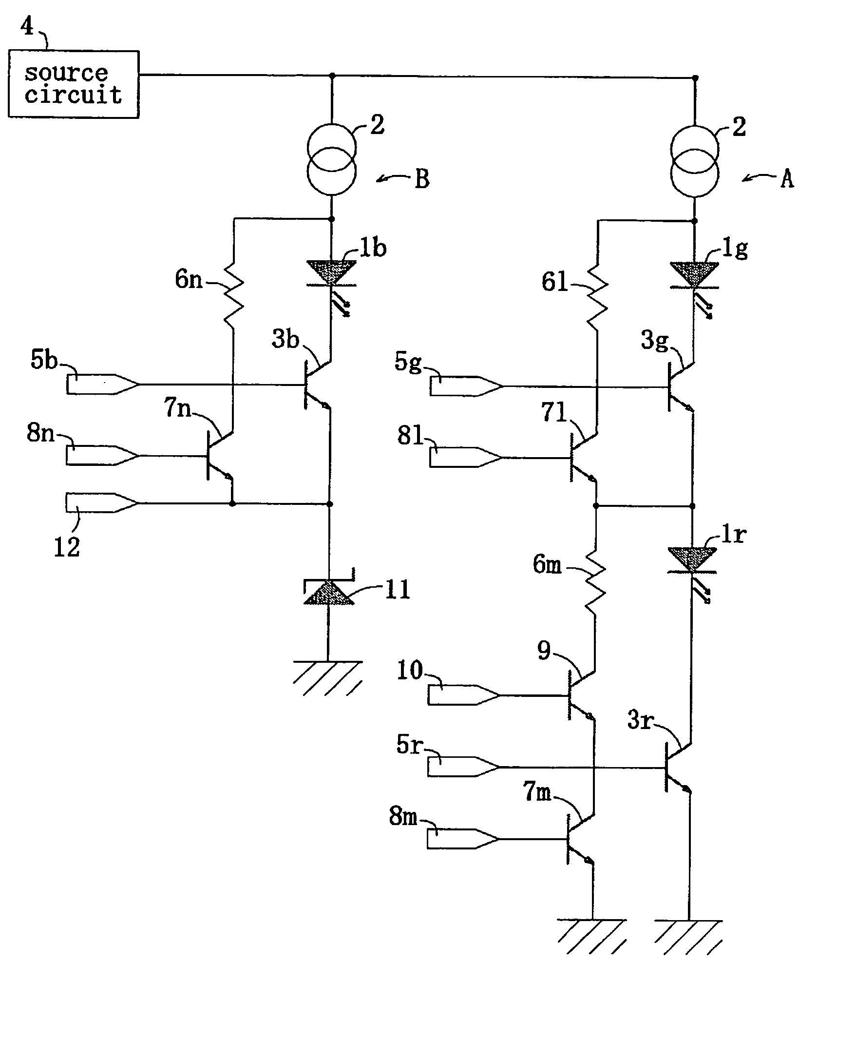
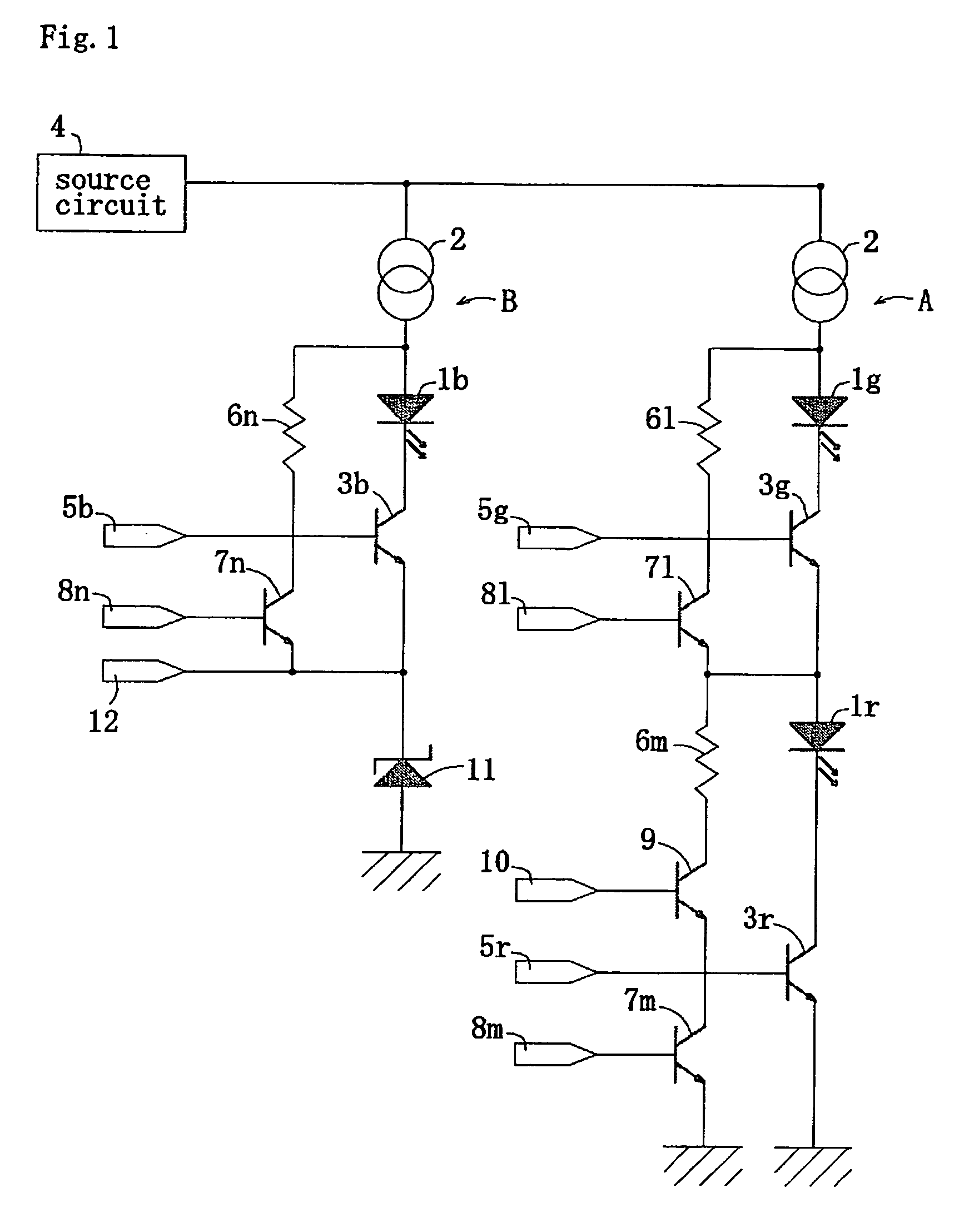
[0019] Embodiments of a display LED drive circuit of the invention will be described below. FIG. 1 is a drawing showing a structure of a display LED drive circuit according to a

[0020] The display LED drive circuit according to the first embodiment is used, for example, for an LED unit of an LED display device that includes a number of LED units connected in series or the like and displays a video picture on a large-sized screen, an LED unit for decorative display such as illumination, or the like, and, as shown in FIG. 1, includes a first current route A and a second current route B, which are connected to a source circuit 4 in parallel, between the source circuit 4 of a DC power source and an earth potential.

[0021] The first current route A is provided with a constant current circuit 2 on an upstream side of a main route, that is, on the side of the source circuit, and a green display LED circuit having a switching element 3g corresponding to a green (G) display LED 1g and being c...
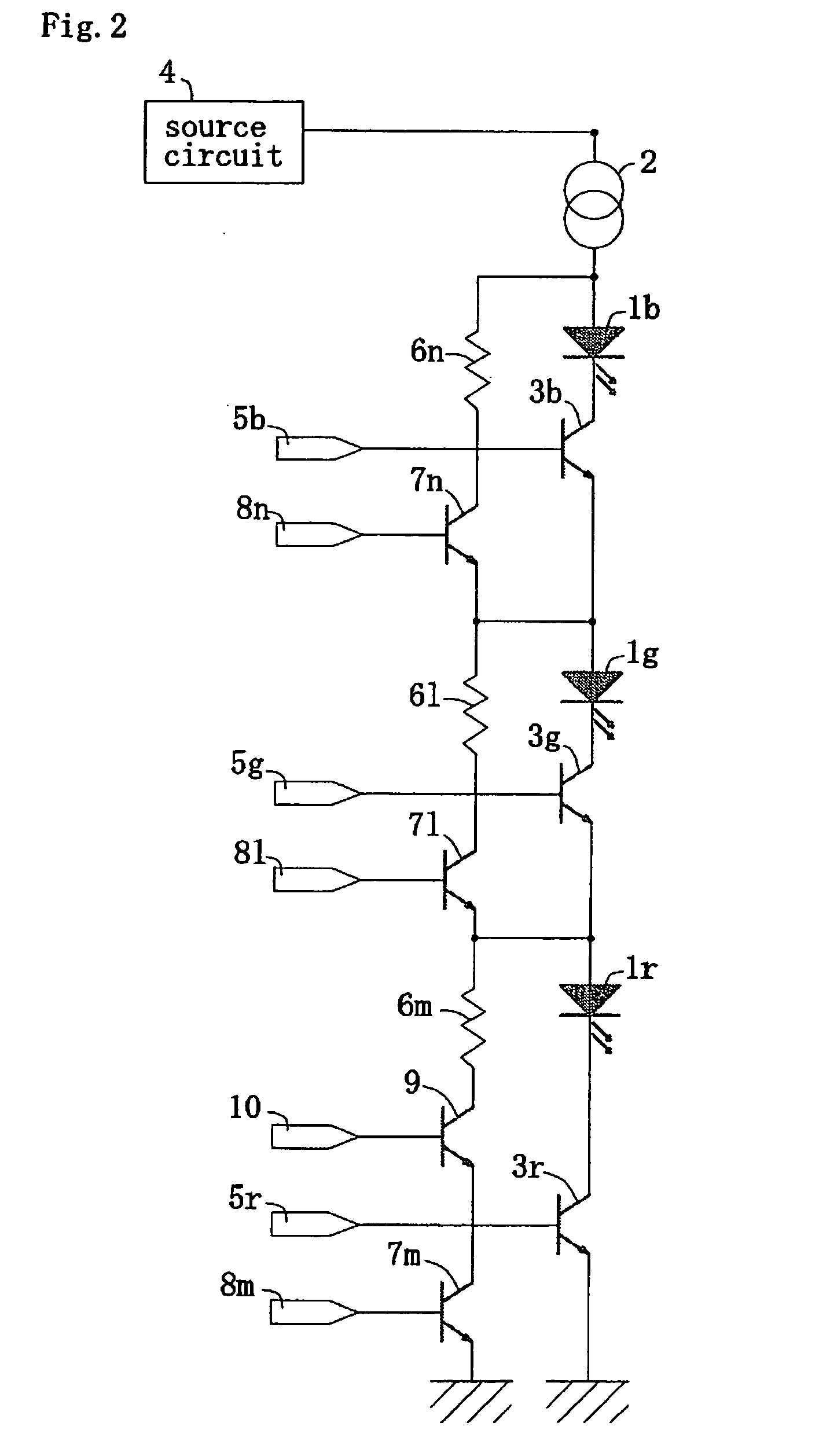
second embodiment

[0041] In the drive circuit the number of the constant current circuits 2 can be reduced to ⅓ of that in the drive circuit in the related art shown in FIG. 3, and hence restriction of increase in temperature of the entire circuit or the cost reduction can be achieved, and the power source usage efficiency can be increased. Also, the switching elements 7 of the respective resistor circuits can be opened and closed exclusively or inversely to the switching elements 3 of the corresponding display LED circuits, so as to apply a desired voltage to the respective display LEDs 1. Also, by restraining the current consumption of the entire circuit to a value required for illuminating one display LED or for the control circuit, and additionally providing the cut-off switching element 9, the reduction of the current consumption is achieved and hence the power can be saved.

[0042] It is also possible to provide a structure in which the cut-off switching element 9 is omitted from the structures ...


PUM


Abstract

A display LED drive circuit configured in such a manner that, for example, a constant current circuit, a green display LED circuit, and a red display LED circuit are connected in series and a resistor circuit having a resistor that generates a potential difference identical to the respective display LEDs is connected in parallel to the respective LED circuits, a corresponding switching element of the display LED circuit and a corresponding switching element of the resistor circuit connected in parallel are controlled to be opened and closed in opposite ways, another route connected to a source circuit in parallel is connected to the constant current circuit, a blue display LED circuit connected in parallel to the resistor circuit as described above, and a constant voltage diode in series, and a predetermined voltage is derived from an output terminal by the constant voltage diode and supplied to a control circuit. In this arrangement, the number of constant current circuits can be reduced, and hence reduction of current consumption and cost, and improvement of the power source usage efficiency are achieved.

Description

TECHNICAL FIELD [0001] The present invention relates to a display LED drive circuit for red color (R), green color (G), and blue color (B) used in an LED unit or the like disposed by a large number in an LED display device for displaying a video picture, for example, on a large-sized screen. BACKGROUND ART [0002] Hitherto, a LED display device having a large number of LED units disposed therein for displaying a video picture on a large-sized screen is known. A display LED drive circuit of the LED unit has a structure, for example, as shown in FIG. 3. The drive circuit shown in FIG. 3 has a red display LED 1r, a green display LED 1g, and a blue display LED 1b connected in parallel for a source circuit 4, and the display LEDs 1r, 1g, 1b are connected respectively to a constant current circuit 2 or a current limit circuit, which limits an electric current to a constant quantity and to a switching element 3 in series, and then respective switching elements 3r, 3g, 3b corresponding to th...

Claims


Application Information

Patent Timeline
Patent Type & Authority Applications(United States)
IPC IPC(8): G09G3/32G09G3/14G09F13/20H01L33/00
CPCG09G3/14G09G3/2003G09G3/32G09G2300/0814G09G2300/088H05B33/083H05B33/086H05B45/48H05B45/20
Inventor NAKAJIMA, CHIAKI
Owner KOMADEN CORP
Why Eureka
Try Eureka