Objective lens, optical pickup, and optical information processing apparatus

a technology of optical information processing and object lens, which is applied in the direction of instruments, optical beam sources, disposition/mounting of heads, etc., can solve the problems of coma aberration, inability to perform normal recording/reproduction operations, and difficulty in achieving size reduction and cost reduction with this method

Inactive Publication Date: 2006-09-07
RICOH KK
View PDF9 Cites 15 Cited by
  • Summary
  • Abstract
  • Description
  • Claims
  • Application Information

AI Technical Summary

Benefits of technology

[0049] In the optical pickup according to claim 22, the optical pickup includes: a plurality of light sources for irradiating light of λ1, λ2, and λ3 wavelengths; and the objective lens of claim 4 for converging and irradiating light from these light sources onto an optical recording medium; an optical system forming an incident light beam in an infinite system with respect to the objective lens for the light of the wavelengths of the two optical recording media having substantially the same substrate thickness and forming an incident light beam in a finite system with respect to the objective lens for the light of the remaining wavelength; and a lens driving apparatus for tilting the objective lens in at least in one of a radial direction and a rotation direction of the optical recording medium so that the optical axis of the objective lens is tilted with respect to an incident beam when a light source satisfying two or more of the conditions (1), (2), and (3) is lit.
[0050] In the optical pickup according to claim 23, the optical pickup includes: a plurality of light sources for irradiating light of λ1, λ2, and λ3 wavelengths; and the objective lens of claim 4 for converging and irradiating light from these light sources onto an optical recording medium; an optical system forming an incident light beam in an infinite system with respect to the objective lens for the light of the wavelengths of the two optical recording media having substantially the same numerical aperture on the optical recording medium side and forming an incident light beam in a finite system with respect to the objective lens for the light of the remaining wavelength; and a lens driving apparatus for tilting the objective lens in at least in one of a radial direction and a rotation direction of the optical recording medium so that the optical axis of the objective lens is tilted with respect to an incident beam when a light source satisfying two or more of the conditions (1), (2), and (3) is lit.

Problems solved by technology

It is, however, difficult to achieve size reduction and cost reduction with this method.
As for other problems, increasing the numerical aperture of the objective lens or shortening the wavelength of the light source leads to a problem of coma aberration created by the tilt (inclination) of the optical recording medium.
A normal recording / reproduction operation cannot be performed since the spot formed on the information recording surface of the optical recording medium degrades when coma aberration occurs.
In a case where the tilt of the optical recording medium is optically corrected by tilting the optical pickup or the carriage part for moving the optical pickup, there are difficult problems such as insufficient responsiveness to tilt correction movement and difficulty in tilting the optical pickup or the carriage at a high speed owing to the fact that the object subjected to tilting is large and heavy.
Furthermore, since a mechanism for tilting the optical pickup or the carriage is required, the optical pickup or the carriage tends to become heavy, to thereby make it difficult to achieve high speed access.
However, coma aberration cannot be cancelled in a case of using such objective lens 110 with a DVD type medium with the finite optical system.
In this case, there is a problem in that the coma aberration caused by the tilting of the optical recording medium 111 of 31(b) cannot be corrected no matter how the objective lens 110 is moved.

Method used


Image

  • Objective lens, optical pickup, and optical information processing apparatus
  • Objective lens, optical pickup, and optical information processing apparatus
  • Objective lens, optical pickup, and optical information processing apparatus

Examples


third embodiment

of the Objective Lens

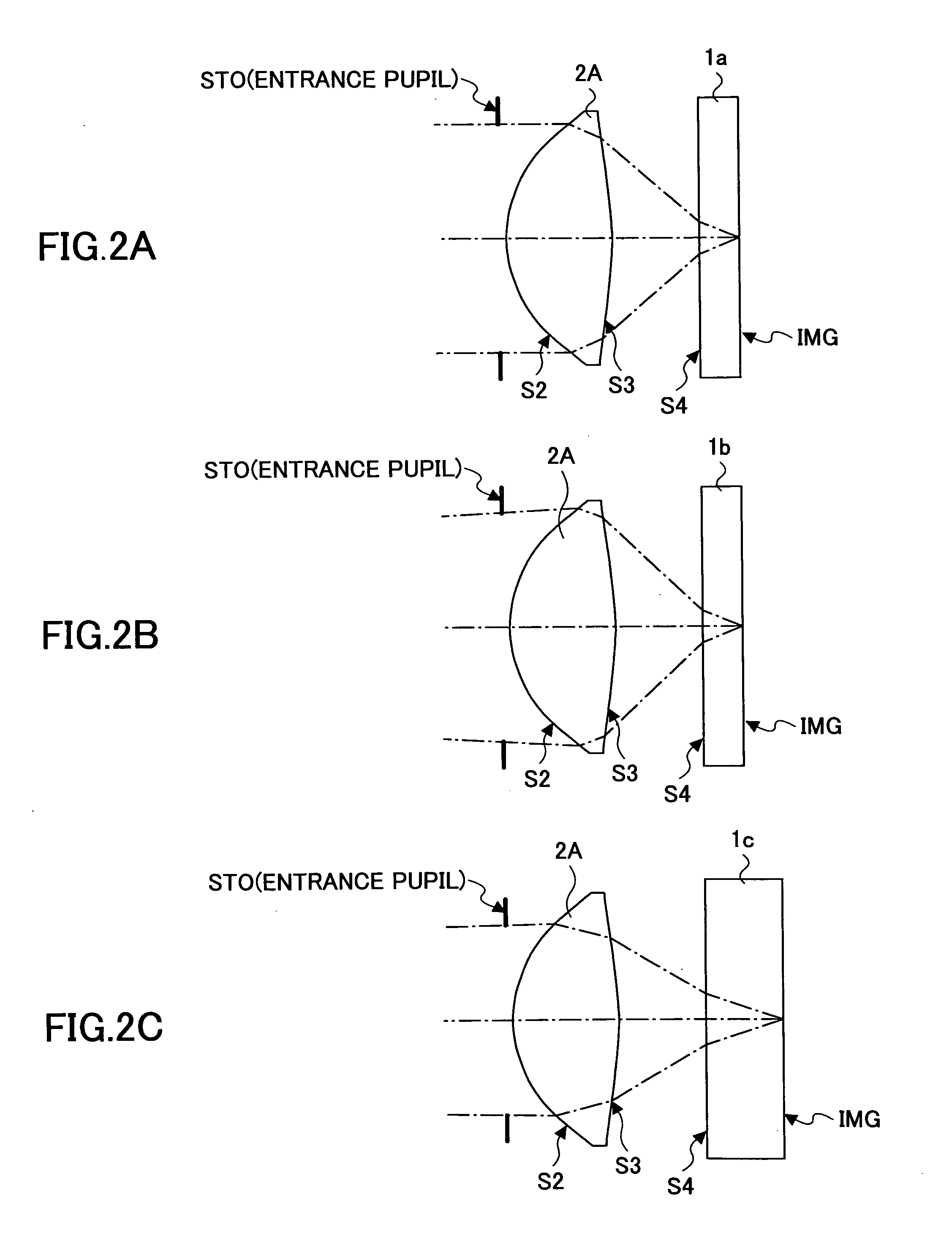
[0117] This embodiment is described with reference to FIGS. 10 to 13. The objective lens 2C of this embodiment is used in an optical pickup for performing a recording process, a reproducing process or an erasing process on three types of optical recording media including a blue type optical recording medium 1a (wavelength (λ1): 405 nm, substrate thickness: 0.6 mm, numerical aperture (NA): 0.65), a DVD type optical recording medium 1b (wavelength (λ2): 660 nm, substrate thickness: 0.6 mm, numerical aperture (NA): 0.65), and a CD type optical recording medium 1c (wavelength (λ3): 785 nm, substrate thickness: 1.2 mm, numerical aperture (NA): 0.50).

[0118] The objective lens 2C of this embodiment is different from the objective lenses 2A, 2B of the first and second embodiments in that the objective lens 2C employs a one group two element configuration instead of a single element configuration. It is generally known that chromatic aberration can be corrected by apply...

first embodiment

of Optical Pickup

[0126] This embodiment of the present invention is described with reference to FIGS. 14-24.

[0127]FIG. 14 is a schematic drawing of an exemplary configuration of an optical pickup for recording, reading out, and / or erasing information in an optical recording medium. The recording or reading out of the information by condensing a light beam from a fixed optical system 3 to an optical recording medium 1 via the objective lens 2 and obtaining signals of the light beam reflected from the optical recording medium 1 from a detecting system (not shown) provided in the fixed optical system 3. Furthermore, other than the fixed optical system 3, an actuator part 4 serving as a lens driving apparatus for tilting the objective lens 2 and a tilt detecting part 5 for detecting the tilt of the optical recording medium 1 are included in the optical pickup. The objective lens 2 is tilted by the actuator part 4 in accordance with the amount of tilt detected by the tilt detecting part...

second embodiment

of Optical Pickup

[0155] This embodiment of the present invention is described with reference to FIGS. 32-34. The optical pickup of this embodiment is for performing recording, read-out, or erasing on two types of optical recording media including a blue type optical recording medium (wavelength λ1: 405 nm, NA: 0.65, thickness of light source side substrate: 0.6 mm) and a DVD type optical recording medium (wavelength λ2: 660 nm, NA: 0.65, thickness of light source side substrate: 0.6 mm).

[0156]FIG. 32 is a schematic drawing showing an exemplary configuration of an optical pickup 200 of this embodiment in relation to that shown in FIG. 15. The optical pickup 200 of this embodiment includes: a blue optical infinite system comprising a semiconductor laser 201 of the blue wavelength band, a collimator lens 202, a polarizing beam splitter 203, a dichroic prism 204, a deflecting prism 205, a ¼ wave plate 206, an aperture 207, an objective lens 208, a detecting lens 210, a beam dividing pa...


PUM

PropertyMeasurementUnit
thicknessaaaaaaaaaa
thicknessaaaaaaaaaa
wavelengths λ1aaaaaaaaaa

Abstract

The present invention relates to an objective lens, an optical pickup, and an optical information processing apparatus. Although coma aberration of approximately 0.22 λ rms, 0.14 λ rms, and 0.09 λ rms is generated in a case where blue type, DVD type, and CD type media is tilted 1 degree, respectively, the coma aberration from medium tilt can be corrected by lens tilt by using an objective lens satisfying the conditions of |CLx/CDx|≧1, wherein CDx (x=1,2,3) is the value of each least square error (unit: λ rms) of the third order coma aberration components generated per angle when the substrates of the medium is tilted, wherein CLx (x=1,2,3) is the value of each least square error (unit: λ rms) of the third order coma aberration components generated per angle when the objective lens is tilted during the converging and irradiating to the medium.

Description

CROSS-REFERENCE TO RELATED APPLICATIONS [0001] This application is a U.S. continuation application filed under 35 USC 111(a) claiming benefit under 35 USC 120 and 365(c) of PCT application JP2004 / 011934, filed Aug. 19, 2004, which claims priority to Application Ser. Nos. 2003-315147 and 2004-163082, filed in Japan on Sep. 8, 2003, and Jun. 1, 2004, respectively. The foregoing applications are hereby incorporated herein by reference.BACKGROUND OF THE INVENTION [0002] 1. Field of the Invention [0003] The present invention generally relates to an objective lens, an optical pickup, and an optical information processing apparatus. [0004] 2. Description of the Related Art [0005] In recent years and continuing, optical recording media such as a CD having a recording capacity of 0.65 GB or a DVD having a recording capacity of 4.7 GB are widely used for storing visual information, audio information, and data stored in a computer. Furthermore, the demand for improving and increasing recording...

Claims


Application Information

Patent Timeline
Patent Type & Authority Applications(United States)
IPC IPC(8): G11B7/00G02B13/18G02B13/00G11B7/09G11B7/095G11B7/125G11B7/1275G11B7/135G11B7/1374G11B7/1392
CPCG11B7/0956G11B7/1275G11B7/1374G11B7/13925G11B2007/0006
Inventor HIRAI, HIDEAKIINOUE, HIROYUKI
Owner RICOH KK
Why Eureka
Try Eureka