Process for synthesis gas production

a technology of synthesis gas and process, applied in the direction of inorganic chemistry, ammonia preparation/separation, use of liquid separation agent, etc., can solve the problem of negative influence on the cost-effectiveness of the entire process

Inactive Publication Date: 2006-09-07
CASALE SA
View PDF5 Cites 5 Cited by
  • Summary
  • Abstract
  • Description
  • Claims
  • Application Information

AI Technical Summary

Problems solved by technology

Such an essential recovery of pressure means a compression of the gaseous fluid from a particularly low pressure value, generally around 20 bar as determined by the aforementioned expansion, and this negatively influences the cost-effectiveness of the entire process.

Method used


Image

  • Process for synthesis gas production
  • Process for synthesis gas production

Examples


Embodiment Construction

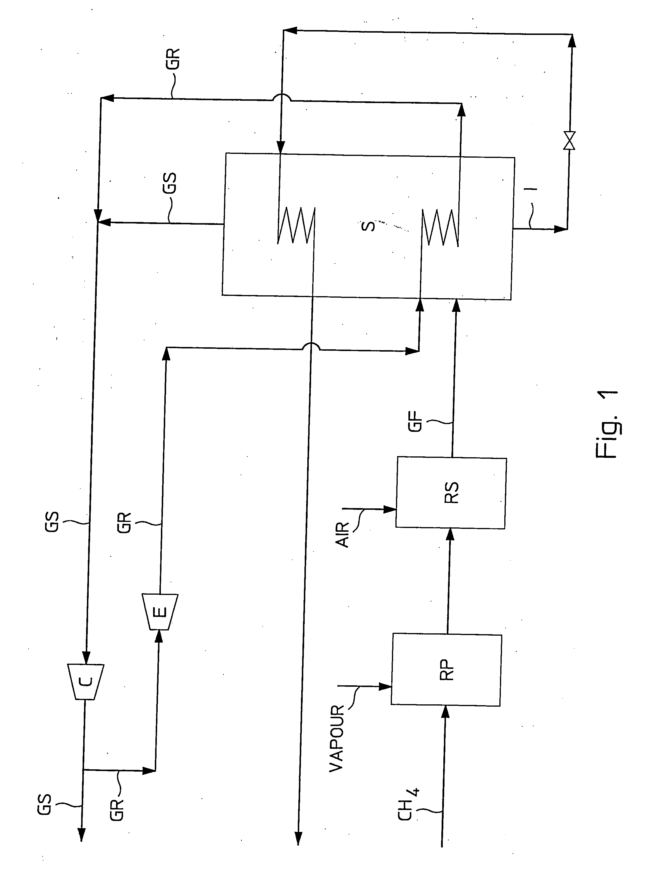
[0023] With reference to FIG. 1, an embodiment of the process according to the invention for obtaining a synthesis gas GS at a predetermined high pressure value, generally between 25 and 30 bar, comprising an amount of hydrogen (H2) and of nitrogen (N2) in a 3 / 1 molar ratio which is particularly suitable for being used in the production of ammonia (NH3) shall now be described.

[0024] In a stationary operating condition, a gaseous flow of methane (CH4) is sent in succession to a first conventional reforming step with steam, or primary reforming RP, and then to a second conventional reforming step with excess air, or secondary reforming RS.

[0025] The gaseous flow GF in output from the secondary reforming RS, comprising hydrogen, nitrogen, impurities and inerts such as carbon oxides, water, argon, is then subjected to a purification step in a separator unit S comprising cryogenic rectification, from which are obtained in output: as head product the synthesis gas GS comprising hydrogen...


PUM

PropertyMeasurementUnit
temperatureaaaaaaaaaa
pressureaaaaaaaaaa
pressureaaaaaaaaaa

Abstract

A process for obtaining a synthesis gas (GS) at a predetermined high pressure corresponding to the ammonia synthesis pressure, in which there are hydrogen and nitrogen in a 3 / 1 molar ratio, comprising the steps of feeding a continuous flow of natural gas to a primary reforming step (RP) with steam and to a subsequent secondary reforming step (RS) with excess air obtaining a gaseous flow (GF) comprises hydrogen, excess nitrogen with respect to said molar ratio, undesired substances such as impurities and inerts and subjects said gaseous flow to a purification step comprising cryogenic rectification in a separator unit (S) obtaining a continuous flow of synthesis gas (GS) comprising hydrogen and nitrogen in a 3 / 1 molar ratio, and to a subsequent compression step up to a pressure value required for ammonia synthesis.

Description

FIELD OF APPLICATION [0001] The present invention refers, in its most general aspect, to a process for synthesis gas production intended to produce ammonia in which a continuous flow of natural gas, for example methane, is subjected to a reforming step with steam (primary reforming), then to a reforming step with excess air (secondary reforming) and then to a purification step comprising cryogenic rectification of the gaseous flow produced in said secondary reforming step. [0002] In particular, the present invention refers to the cryogenic purification step of a process of the aforementioned type, to obtain pure synthesis gas at a predetermined pressure. PRIOR ART [0003] It is known that to obtain synthesis gas (H2+N2) intended for ammonia production, a continuous flow of natural gas, in particular methane (CH4), is subjected to reforming treatments, firstly with steam and then with excess air, called primary reforming and secondary reforming, respectively. [0004] The gaseous produc...

Claims


Application Information

Patent Timeline
Patent Type & Authority Applications(United States)
IPC IPC(8): C01B3/02B01J8/02
CPCC01B3/025C01B3/382C01B3/506C01B2203/0233C01B2203/0244C01B2203/046C01B2203/0465C01B2203/047C01B2203/0475C01B2203/0495C01B2203/068C01B2203/0816C01B2203/0844C01B2203/143C01B2203/82F25J3/0219F25J3/0276F25J2200/74F25J2200/80F25J2210/04F25J2210/20F25J2245/02F25J2270/04
Inventor FILIPPI, ERMANNOSKINNER, GEOFFREY FREDERICK
Owner CASALE SA
Why Eureka
Try Eureka