
Method for controlling the adjustment of the valves in a combustion engine with variable valves and a vehicle with such an engine with electronic controlling device for the valve control

a technology of electronic control device and valve control, which is applied in the direction of electrical control, non-mechanical valves, machines/engines, etc., can solve the problems of low internal exhaust recirculation and unwanted delays

Inactive Publication Date: 2006-09-07
VOLVO LASTVAGNAR AB
View PDF5 Cites 46 Cited by
  • Summary
  • Abstract
  • Description
  • Claims
  • Application Information

AI Technical Summary

Benefits of technology

The present invention provides a method for controlling the adjustment of valves in an engine with variable valves to match future changes in valve timing and lift height. This is done by calculating the future resistance to forward motion and the time to a future transient in the engine's operating condition, and making necessary adjustments to the valves in advance. This allows for better engine performance in different driving conditions and avoids disturbances during mode changes or torque increases. The invention also includes controlling low internal exhaust recirculation to avoid negative pressure ratio and improves engine compression braking during gear changes. The controlling devices use information about the vehicle's resistance to forward motion and the engine's operating condition to optimize engine performance.

Problems solved by technology

During the changeover from one operating mode to a second operating mode, unwanted delays arise.
The delay is caused, as mentioned above, primarily by the gas volumes in the engine's pipe system on the inlet side, but also by the inertia in the turbo unit, if the engine is equipped with such a unit.
In addition, in the event of an increase in torque, low internal exhaust recirculation is required.

Method used


Image

  • Method for controlling the adjustment of the valves in a combustion engine with variable valves and a vehicle with such an engine with electronic controlling device for the valve control
  • Method for controlling the adjustment of the valves in a combustion engine with variable valves and a vehicle with such an engine with electronic controlling device for the valve control
  • Method for controlling the adjustment of the valves in a combustion engine with variable valves and a vehicle with such an engine with electronic controlling device for the valve control

Examples


Embodiment Construction

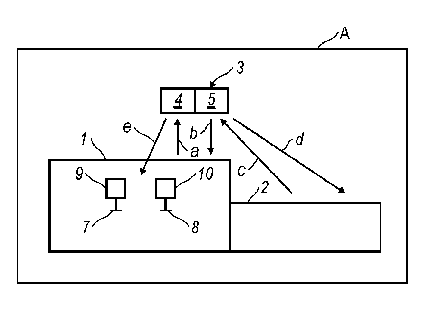
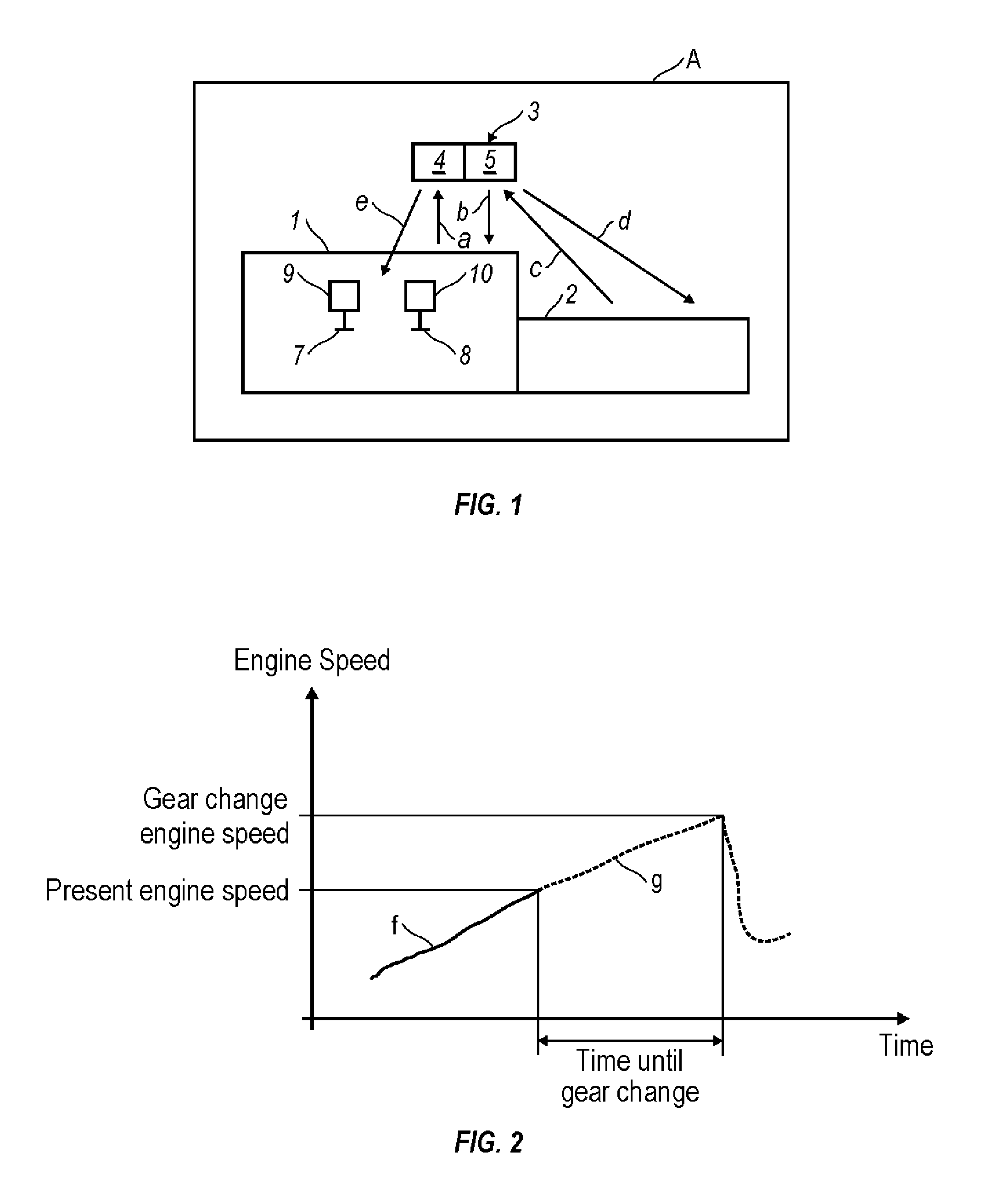
[0018] In FIG. 1, a combustion engine 1 is designated in a vehicle A, to which a transmission 2 is connected in such a way that it is driven by the engine. The engine 1 and the transmission 2 are controlled by an electronic control unit 3, comprising (including, but not necessarily limited to) an engine control part 4 and a transmission control part 5, each of which communicates with the other. The control can be carried out according to the model that is described in the abovementioned SE 0103629-2 and is symbolized by the arrows “a” and “b” for the engine control and by “c” and “d” for the transmission control.

[0019] The engine 1 can be of the multi-cylinder type, for example six-cylinder, Otto cycle or diesel engine, with or without a supercharging system (turbo unit), and with single or double inlet and exhaust valves for each cylinder. In FIG. 1, an inlet valve 7 and exhaust valve 8 are schematically represented with respect to an engine cylinder. Each valve 7 and 8 is provide...


PUM


Abstract

Method and arrangement for providing a vehicle having a combustion engine (1) with valves (7, 8) adapted to have variable valve timing and / or valve lift height. The valves are provided with operating devices (9,10) that are controlled by electronic controlling devices (3), which are arranged, while the vehicle is being driven, with the aid of entered information about at least the gradient of the road and the throttle position, to calculate future resistance to forward motion and the period of time to a future transient in the engine's operating condition, for example in association with a future change of engine operating mode and / or a future gear change in a gearbox (2) connected to the engine. The controlling devices are arranged to control valve timing and / or the valve lift height during the period of time for optimization of the engine's performance, once the transient has arisen.

Description

CROSS-REFERENCE TO RELATED APPLICATIONS [0001] The present application is a continuation patent application of International Application No. PCT / SE2004 / 000881 filed 7 Jun. 2004 which is published in English pursuant to Article 21(2) of the Patent Cooperation Treaty, and which claims priority to Swedish Application No. 0301714-2 filed 12 Jun. 2003. Said applications are expressly incorporated herein by reference in their entireties.FIELD OF THE INVENTION [0002] The present invention relates to a method, in a vehicle with a combustion engine, that has at least an inlet valve and at least an exhaust valve on each combustion chamber, and at least one of which has variable valve timing and / or valve lift height, for regulating said valve's timing and / or valve lift height while the vehicle is being driven. [0003] The invention also relates to a vehicle with a combustion engine that has at least an inlet valve and at least an exhaust valve on each combustion chamber, and at least one of whi...

Claims


Application Information

Patent Timeline
Patent Type & Authority Applications(United States)
IPC IPC(8): B60W10/10F01L1/34B60W10/11B60W30/18F01L9/20F02D13/02F02D21/08F02D41/02F02D41/10
CPCB60K2741/065Y10T477/675B60W2550/142F02D13/0207F02D13/0253F02D13/0261F02D13/0269F02D41/021F02D41/023F02D41/107F02D2041/001F02D2200/701Y02T10/18Y02T10/142Y10T477/68B60W2510/0604B60W10/04B60W10/11B60W30/1819B60W2552/15Y02T10/12
Inventor BERGLUND, SIXTENERIKSSON, ANDERSSTEEN, MARCUSUDD, SOREN
Owner VOLVO LASTVAGNAR AB
Learn More