Mold for casting and method of surface treatment thereof

Inactive Publication Date: 2006-09-14
HONDA MOTOR CO LTD
2 Cites 16 Cited by

AI-Extracted Technical Summary

Problems solved by technology

However, even when the shot peening treatment is merely applied to the casting die, it is impossible to remar...

Benefits of technology

[0024] When the shot peening treatment and the nitriding treatment are applied to the cavity surface of the casting die, it is possible to obtain the casting die provided with the cavity surface in which the compressive residual stress is extremely large and the hardness is high. As described above, such a casting die is excellent in durability. Therefore, the casting die has a long service life.
[0025] The shot peening treatment may be performed earlier than the nitriding treatment, and vise versa. However, it is preferable that the shot peening treatment is performed earlier. In this case, the cavity surface is smoothened by the shot peening treatment. Further, the compressive stress is applied to the cavity surface. Therefore, the nitrogen atom and the sulfur atom are bonded to Fe with ease in the sulphonitriding treatment.
[0026] When the shot peening treatment is performed earlier, it is preferable that the shot peening treatment is performed again after applying the nitriding treatment so that the maximum height of the cavity surface is not more than 8 μm, and the compressive residual ...

Abstract

A method of the surface treatment of a mold for casting, which comprises subjecting a cavity surface of a fixed mold made by the use of a SCM420 material to first shot peening, a sulfurizing-nitriding treatment and second shot peening. The resulting cavity surface of the fixed mold exhibits a high hardness of 700 or higher in terms of Vickers hardness due to the presence of a sulfurized and nitrided layer, and further has a compression residual stress of more than 1200 Mpa and a largest height, which is a surface roughness value defined by JIS standard, of 8 μm or less.

Application Domain

Technology Topic

HardnessShot peening +2

Image

  • Mold for casting and method of surface treatment thereof
  • Mold for casting and method of surface treatment thereof
  • Mold for casting and method of surface treatment thereof

Examples

  • Experimental program(1)

Example

[0033] The casting die of the present invention and the surface treatment method thereof will be explained in detail below with reference to the accompanying drawings as exemplified by preferred embodiments.
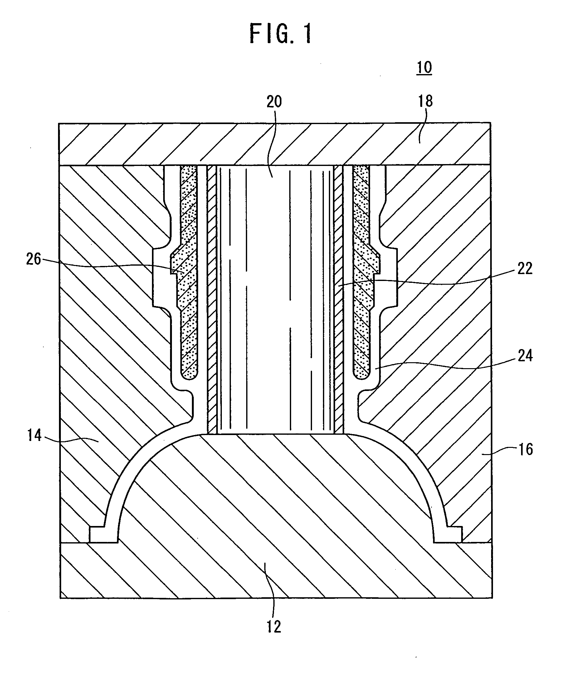
[0034]FIG. 1 is a schematic vertical sectional view illustrating a casting apparatus provided with a casting die according to an embodiment of the present invention. The casting apparatus 10 is usable to cast an unillustrated cylinder block as a cast product of aluminum. The casting apparatus 10 comprises casting dies, i.e., a fixed die 12, side movable dies 14, 16, and an upper movable die 18. In particular, the fixed die 12 is provided with a bore pin 20. A sleeve 22 is externally installed to the bore pin 20, and thus a cavity 24 for obtaining the cylinder block is formed in the casting apparatus.
[0035] A sand-core 26, which is provided to form a water jacket of the cylinder block, is arranged in the cavity 24. The sand-core 26 is supported by an unillustrated support member.
[0036] Each of the fixed die 12, the side movable dies 14, 16, and the upper movable die 18 has a base material layer of a steel material represented as SCM420 by Japanese Industrial Standard. As shown in FIG. 2, a sulphonitrided layer 32, which is formed on the base material layer 30 of the SCM420 material, is present at the cavity surface of each of the dies 12, 14, 16, 18. The sulphonitrided layer 32 is a diffusion layer obtained by diffusing, in the base material layer 30, the sulfur atom and the nitrogen atom originating from a sulfurizing gas and a nitriding gas simultaneously supplied to the base material layer 30 as described later on. The sulphonitrided layer 32 contains a nitrided layer and iron sulfide.
[0037] The iron nitride contained in the sulphonitrided layer 32 improves the hardness of the SCM420 material (fixed die 12). That is, if the sulphonitrided layer 32 exists, the cavity surface of the fixed die 12 has high hardness. Specifically, the cavity surface exhibits a Vickers hardness of about 700.
[0038] The iron sulfide contained in the sulphonitrided layer 32 is a component for applying lubrication performance to the fixed die 12. In other words, the lubrication performance of the fixed die 12 is remarkably improved owing to the presence of the iron sulfide. As a result, it is possible to prevent the occurrence of scuffing or galling.
[0039] The thickness of the sulphonitrided layer 32 is preferably not less than 0.1 mm in order to give the sufficient hardness to the surface layer portion and the cavity surface of the fixed die 12, because the SCM420 material as the material of the fixed die 12 is soft. In order to give the sufficient hardness to the fixed die 12, it is sufficient that the thickness of the sulphonitrided layer 32 is about 0.2 mm at the maximum.
[0040] The maximum height (hereinafter referred to as “Ry” as well), which is obtained with a sampling length of 0.8 mm and an evaluation length of 4 mm at the cavity surface of the fixed die 12, is set to be not more than 16 μm.
[0041] Ry is determined as defined in JIS B 0601-2001, which is an index to express the roughness of the cavity surface. That is, as shown in FIG. 3, when a portion of the roughness profile CV to represent the minute irregularities of the cavity surface is sampled or extracted in an amount corresponding to the sampling length in the direction of the mean line, Ry represents the difference in height between the lowest valley 40 and the highest peak 42 of the extracted portion.
[0042] As described above, the sampling length is 0.8 mm and the evaluation length is 4 mm in this embodiment. The mean line is a straight line determined by the least square method on the basis of the depths of the respective valleys and the heights of the respective peaks within the sampling length of 0.8 mm.
[0043] The fixed die 12, in which Ry at the cavity surface is not more than 16 μm, can be obtained by applying a shot peening treatment as described later on. Further, Ry of the cavity surface can be made to 8 μm or less as well by performing the shot peening treatment twice.
[0044] The compressive residual stress is larger than 1000 MPa in the fixed die 12 to which the shot peening treatment has been applied. In particular, when the shot peening treatment is performed twice, the compressive residual stress exhibits a value larger than 1200 MPa.
[0045] The respective cavity surfaces of the side movable dies 14, 16 and the upper movable die 18 may also be constructed in the same manner as described above.
[0046] The fixed die 12, which is constructed as described above, can be obtained as follows. That is, first, starting from the SCM420 material as a raw material, the fixed die 12 is manufactured in accordance with a known processing method.
[0047] Subsequently, the shot peening treatment for coarse processing is applied to the cavity surface of the fixed die 12 in a first shot peening step. Specifically, water including ceramic particles having particle diameters of 200 to 220 meshes is allowed to collide against the cavity surface. In this procedure, the following condition may be available. For example, the discharge pressure of a pump for discharging the water containing the ceramic particles is 0.39 to 0.59 MPa (4 to 6 kgf/cm2), and the ceramic particles make the collision for 5 to 10 seconds per 5 cm2 of the cavity surface. Accordingly, the compressive stress of about 1.5 to 2.0 MPa (15 to 20 kgf/cm2) is applied to the cavity surface.
[0048] As a result of the first shot peening step, Ry of the cavity surface is about 12 to 16 μm, and the compressive residual stress is 1000 MPa.
[0049] Subsequently, the fixed die 12, which has undergone the first shot peening step, is accommodated in a processing chamber to apply a sulphonitriding treatment. That is, the temperature in the processing chamber is maintained at 505° to 580° C., preferably about 570° C. After that, ammonia gas, hydrogen sulfide gas, and hydrogen gas are supplied into the processing chamber. The nitrogen atom as the constitutive element of the ammonia gas and the sulfur atom as the constitutive element of the hydrogen sulfide are diffused and bonded with respect to Fe as the constitutive element of the SCM420 material (fixed die 12). Accordingly, iron nitride and iron sulfide are produced. As a result, the sulphonitrided layer 32 is formed.
[0050] As described above, the cavity surface has been smoothened by means of the first shot peening treatment. Further, the compressive stress is applied to the cavity surface. Therefore, the nitrogen atom and the sulfur atom are bonded to Fe with ease when the sulphonitriding treatment is applied. That is, the sulphonitriding is advanced with ease.
[0051] The hydrogen gas is a component to control the activities of the ammonia gas and the hydrogen sulfide gas. It is possible to prevent the SCM420 material from being corroded by the ammonia gas by supplying the predetermined amount of hydrogen gas.
[0052] Subsequently, a shot peening treatment for finishing processing is applied to the cavity surface of the fixed die 12 in a second shot peening step. The second shot peening step may be performed under a condition that water including glass particles having particle diameters of 200 to 220 meshes, makes the collision for 5 to 10 seconds per 5 cm2 of the cavity surface, while the discharge pressure of the pump is, for example, 0.29 to 0.49 MPa (3 to 5 kgf/cm2).
[0053] As a result of the second shot peening step, Ry of the cavity surface is about 4 to 8 μm, and the compressive residual stress is larger than 1200 MPa.
[0054] Thus, the fixed die 12 is consequently obtained, in which the sulphonitrided layer 32 is provided at the cavity surface, Ry of the cavity surface is not more than 8 μm, and the compressive residual stress is larger than 1200 MPa. Of course, when the same or equivalent surface treatment is applied to the respective cavity surfaces of the side movable dies 14, 16 and the upper movable die 18, it is possible to construct the side movable dies 14, 16 and the upper movable die 18 having the cavity surfaces as described above.
[0055] The cylinder block is manufactured as follows by using the casting dies constructed as described above.
[0056] First, for example, molten metal such as aluminum is supplied into the cavity 24 via an unillustrated runner and an unillustrated gate, while the fixed die 12, the side movable dies 14, 16, and the upper movable die 18 are clamped as shown in FIG. 1. The supplied molten metal is cast with high pressure, i.e., at a pressure of about 85 MPa to 100 MPa.
[0057] During this process, even when the tensile stresses are exerted on the dies 12, 14, 16, 18 as the molten metal is supplied, the tensile stresses do not exceed the compressive residual stresses, because the compressive residual stresses of the fixed die 12, the side movable dies 14, 16, and the upper movable die 18 are remarkably large. Accordingly, the dies 12, 14, 16, 18 are excellent in the thermal shock resistance. Therefore, the heat crack in the dies 12, 14, 16, 18 is prevented, and hence the service lives of the dies 12, 14, 16, 18 are prolonged.
[0058] Further, the reaction between the aluminum (molten metal) and the respective dies 12, 14, 16, 18 is also prevented, because the sulphonitrided layer 32 is provided at each of the cavity surfaces.
[0059] The aluminum molten metal processed by the high pressure casting is solidified as the dies are cooled. After the completion of the solidification, the upper movable die 18 and the side movable dies 14, 16 are separated from the fixed die 12 to open the dies. Subsequently, the cast product, i.e., the cylinder block is taken out by using an unillustrated knockout pin.
[0060] During this process, the cutting of the cavity surface, which would be otherwise caused by the sliding contact with the cast product, is remarkably prevented, because the Vickers hardness of each of the cavity surfaces is not less than 700 because of the sulphonitrided layer 32. That is, the cavity surfaces are prevented from the chipping.
[0061] Further, in this procedure, the frictional resistance between the cylinder block and the cavity surface is remarkably small, because the iron sulfide is contained in the sulphonitrided layer 32. Therefore, any appearance of the scuffing or galling can be prevented as well.
[0062] When the casting operation is repeated, the compressive residual stress of each of the dies 12, 14, 16, 18 is progressively decreased. Therefore, heat crack will appear in the dies 12, 14, 16, 18 some time. In order to avoid this inconvenience, the first shot peening treatment, the sulphonitriding treatment, and the second shot peening treatment may be applied again as described above to the dies 12, 14, 16, 18 in each of which the compressive residual stress has been decreased. Accordingly, it is possible to increase the compressive residual stress of each of the dies 12, 14, 16, 18 again. Thus, it is possible to further prolong the period of time until a heat crack appears.
[0063] That is, the surface treatment method according to the embodiment of the present invention is applicable not only to the dies 12, 14, 16, 18 before being used for the casting operation but also to the dies 12, 14, 16, 18 in each of which the compressive residual stress is lowered as a result of the repeated use for the casting operation. Accordingly, it is possible to further prolong the service life of each of the dies 12, 14, 16, 18.
[0064] As described above, the service life of each of the dies 12, 14, 16, 18 can be prolonged by applying the shot peening treatment and the nitriding treatment to the dies 12, 14, 16, 18. Therefore, the replacement frequency of each of the dies 12, 14, 16, 18 is decreased to be as low as possible. Thus, it is possible to reduce the production cost of the cylinder block as the cast product.
[0065] In the embodiment of the present invention, the shot peening treatment is performed twice. However, the shot peening treatment may be performed once. In this procedure, the shot peening treatment may be performed after performing the sulphonitriding treatment.
[0066] It goes without saying that the shot peening treatment and the nitriding treatment may be applied to the entire surfaces as well as the cavity surfaces of the fixed die 12, the side movable dies 14, 16, and the upper movable die 18.
[0067] The foregoing embodiment has been explained as exemplified by the casting die of the SCM420 material. However, there is no special limitation thereto. The present invention is applicable to any casting die provided that the casting die is made of a steel material. For example, the present invention is also applicable to a casting die of a SKD61 material. In this case, the sufficient thickness of the sulphonitrided layer 32 is 0.03 mm.
[0068] The sulphonitrided layer 32 may be obtained such that a compound layer of iron sulfide and iron nitride is formed on the diffusion layer. In this case, the thickness of the compound layer is preferably not more than 6 μm in order to avoid the increase in brittleness.
[0069] A nitrided layer may be provided in place of the sulphonitrided layer 32 by adopting the gas nitriding in place of the sulphonitriding.
[0070] As explained above, the compressive residual stress remains and the nitrided layer is formed at the cavity surface by applying the shot peening treatment and the nitriding treatment to at least the cavity surface of the casting die of the steel material. Accordingly, the thermal shock resistance is improved, and the surface of the casting die becomes hard. Therefore, the heat crack and the chipping scarcely appear in the casting die, and hence the service life of the casting die is remarkably prolonged. That is, the replacement frequency of the casting die is reduced. Consequently, it is possible to reduce the production cost of the cast product.

PUM

PropertyMeasurementUnit
Length8.0E-6m
Length1.6E-5m
Length1.0E-4m
tensileMPa
Particle sizePa
strength10

Description & Claims & Application Information

We can also present the details of the Description, Claims and Application information to help users get a comprehensive understanding of the technical details of the patent, such as background art, summary of invention, brief description of drawings, description of embodiments, and other original content. On the other hand, users can also determine the specific scope of protection of the technology through the list of claims; as well as understand the changes in the life cycle of the technology with the presentation of the patent timeline. Login to view more.

Similar technology patents

Male sexual aid

InactiveUS6991600B1High hardnessIncreases perdurabilityVibration massageNon-surgical orthopedic devicesMale genderFemale humans
Owner:WANG HISN FU

Classification and recommendation of technical efficacy words

  • High hardness
  • Excellent durability
Why Eureka
Try Eureka