Interactive refractor incorporating wavefront sensing and adaptive optics

Inactive Publication Date: 2006-09-14
NOVARTIS AG
View PDF13 Cites 57 Cited by
  • Summary
  • Abstract
  • Description
  • Claims
  • Application Information

AI Technical Summary

Benefits of technology

[0017] The invention involves the integration of a measurement device, such as a wavefront sensor, for measuring higher order aberrations in an eye, with an adaptive optics device, such as an electro-active lens, for correcting the higher order aberrations. This integrated technology, referred to herein as an interactive refractor, not only enables diag

Problems solved by technology

Several refractive defects can occur in the human eye.
Refractive defects prevent rays of light entering the eye from properly focusing into a clear image on the retina of the eye.
These refractive defects may cause a variety of vision problems.
If the eye has too much sphere, light focuses too early within the eye (i.e., in front of the retina), causing myopia or nearsightedness of the eye.
If the eye has too little sphere, light focuses too late (i.e., behind the retina), causing hyperopia or farsightedness of the eye.
In the case of myopia, the eye refracts, or bends, light too much, causing the light to come to a focus point too early.
If the eye has a coma defect, light comes into focus off-center on the retina, leading to vision distortion.
If the eye has a foil defect, the outer edges of the eye's optics are wavy, causing poor vision under darkened viewing conditions.
If the eye has a spherical aberration, light focus gets worse as viewing conditions become darker and the pupil opens up.
The more the pupil opens up, the farther in front of the retina the light focuses, leading to nearsightedness in darkened conditions.
Since

Method used


Image

  • Interactive refractor incorporating wavefront sensing and adaptive optics
  • Interactive refractor incorporating wavefront sensing and adaptive optics
  • Interactive refractor incorporating wavefront sensing and adaptive optics

Examples


Embodiment Construction

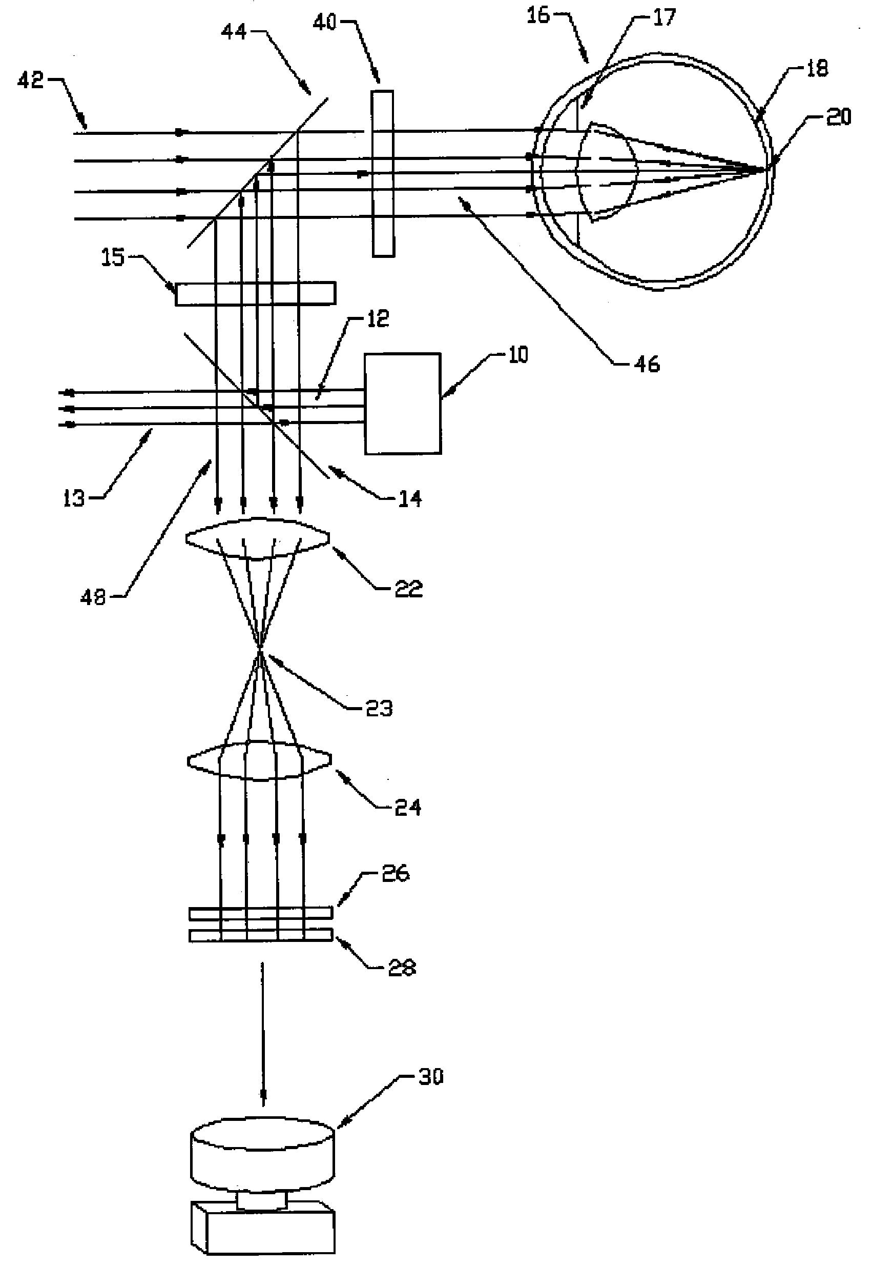
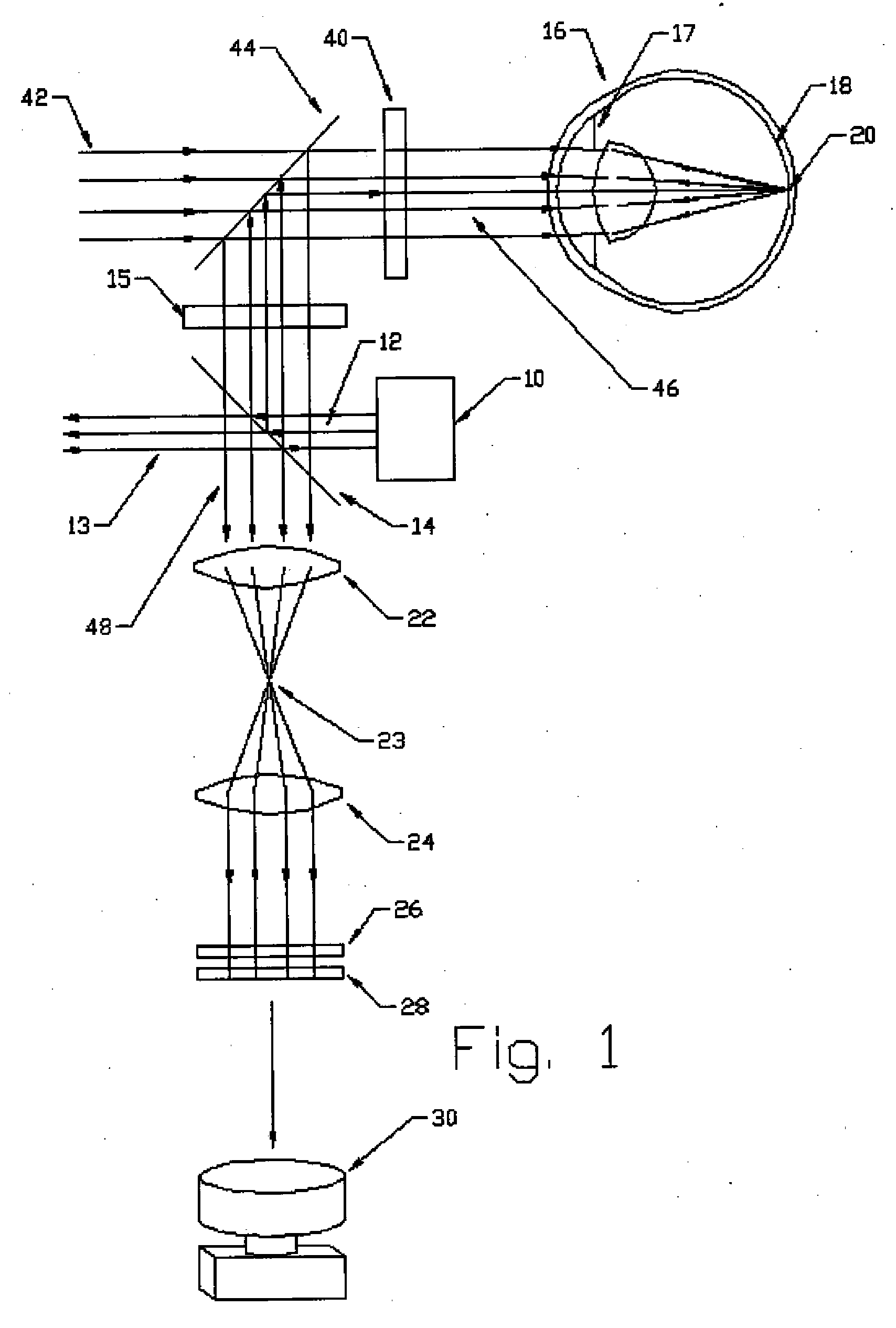
[0026]FIG. 1 is a schematic illustration of an interactive refractor system according to a preferred embodiment. The interactive refractor system includes a light source 10, such as a laser generator, for directing a broad, collimated light beam 12 toward a beam splitter 14. The light source 10 preferably generates a light beam 12 having a wavelength of 500 to 1000 nm, more preferably 700 to 800 nm, more preferably 770 to 790 nm. The diameter or cross-sectional area of the beam is preferably at least as large as the area of the surface of the eye to be measured. For example, if the refractive properties of the central 3 mm diameter of the eye are to be measured, then the beam should be at least 3 mm in diameter, and be incident upon the 3 mm diameter of the eye.

[0027] At approximately 780 nm, the light beam 12 is virtually invisible (other than a small, central spot) to the human eye, which provides for optimal analysis, since the eye does not react to the entering light. If visibl...


PUM


Abstract

An integrated wavefront sensor and adaptive optic system includes an electroactive lens (40) positioned such that light from real world objects (42) being observed by a patient is combined, by a combiner optic (44), with a wavefront sensor illumination beam (12) into a single beam of light (46) that passes through or onto the electroactive lens (40). With this integrated system, the patient's vision may be measured and corrected, taking into account changes in the higher order aberrations that are influenced by the patient's accommodation, simultaneous to the patient observing, in real time, the refractive correction being proposed.

Description

PRIORITY CLAIM [0001] This application is a continuation of International Application Serial No. PCT / US2004 / 040425, filed Dec. 2, 2004, which claims the benefit of U.S. Provisional Application Ser. No. 60 / 526,176, filed Dec. 2, 2003. Priority to both of these applications is claimed, and both of the applications are incorporated herein by reference.FIELD OF THE INVENTION [0002] The present invention is generally in the field of optics, specifically for measuring aberrations in the eye. BACKGROUND OF THE INVENTION [0003] Several refractive defects can occur in the human eye. Refractive defects prevent rays of light entering the eye from properly focusing into a clear image on the retina of the eye. When an eye is focusing properly, a beam of parallel light rays entering the eye will converge to a single point of light on the retina. When an eye cannot do this, because it has refractive errors, the light does not come to a point at the retina, and instead forms a diffuse blob on the r...

Claims


Application Information

Patent Timeline
IPC IPC(8): A61B3/10A61B3/00G02B
CPCA61B3/103
Inventor VAN HEUGTEN, ANTHONY Y.
Owner NOVARTIS AG
Why Eureka
Try Eureka