
Router selecting method and router apparatus

a router and router technology, applied in the field of routers, can solve the problems of inability to select and use the router having the optimum access interface, the inability to operate the ip telephone requiring reliability, and the inability to use the wireless lan router to perform an ftp requiring a broadband, so as to improve the degree of freedom of access capability information, the effect of traffic reduction

Active Publication Date: 2006-09-14
APPLE INC
View PDF10 Cites 25 Cited by
  • Summary
  • Abstract
  • Description
  • Claims
  • Application Information

AI Technical Summary

Benefits of technology

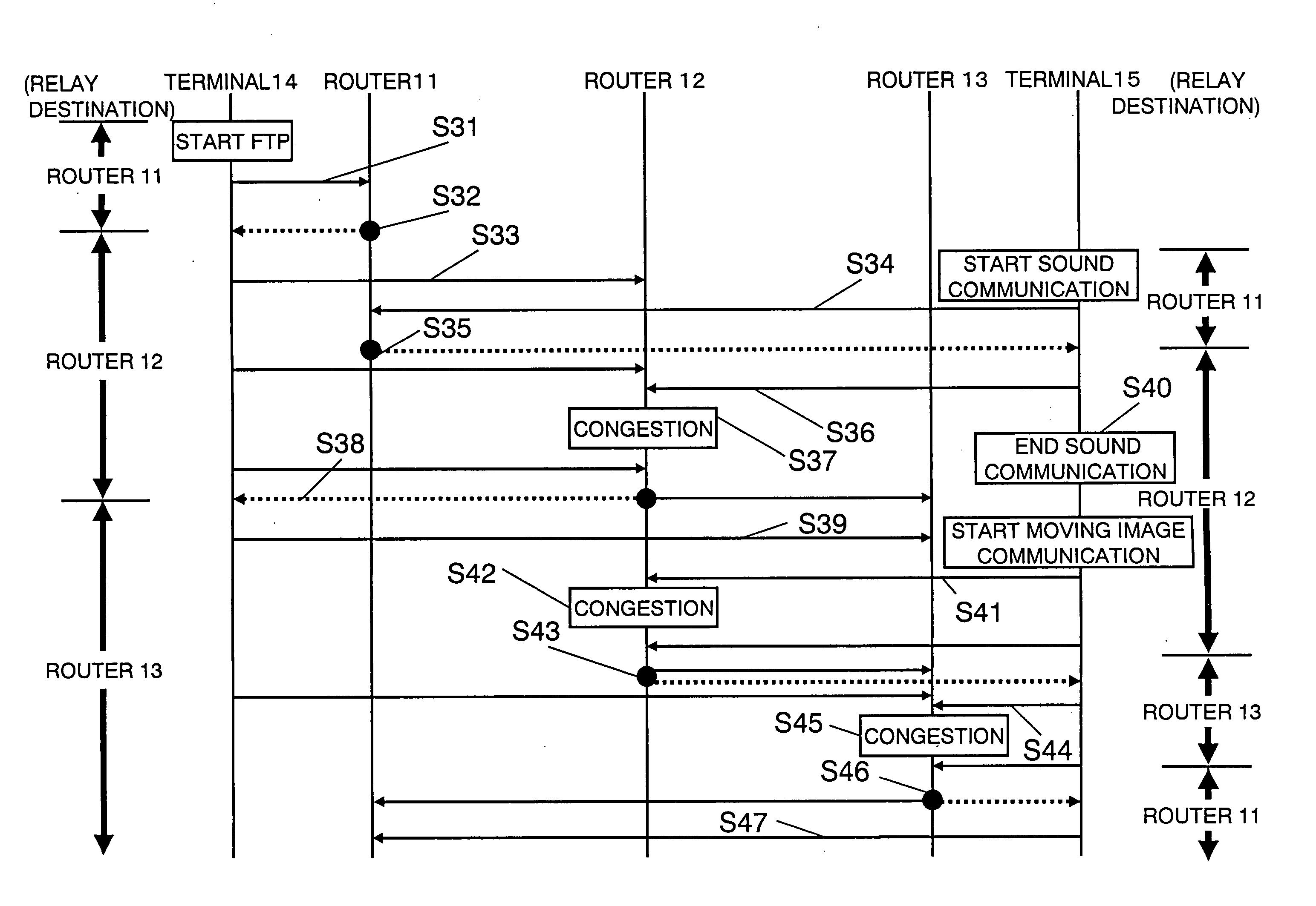
[0014] Thus, in the end a router suitable for relaying the packet is selected. Since the selection of a router is performed only through the redirection of routers, it is possible to make it unnecessary to add a new function to a terminal. Moreover, since a redirect packet is transmitted only after a router capable of relaying the packet is identified, it is possible to restrain increase in network loads due to an increase of redirect packets. Since a terminal has to change a path only once, it is possible to reduce processing loads on the terminal.
[0030] Information on access capability of each of the routers only has to be held by that router itself and is not required to be communicated to other routers and terminals. Thus, a message for exchanging access capability information is unnecessary, traffic is reduced, and the degree of freedom of the access capability information itself is improved.

Problems solved by technology

However, in this method, there is only one router that can always be used among the virtual routers.
It is thus impossible to select an appropriate router for a particular case.
Therefore, it is impossible to select and use a router having an optimum access interface according to the demands of an application.
For example, when there is a router with an access interface to a wireless LAN (a wireless LAN router) and a router having an access interface to a cellular network (a cellular router), using the wireless LAN router to perform an FTP requiring a broadband and using the cellular router to operate an IP telephone requiring reliability is impossible.
However, in the conventional constitution, since the terminal selects a router, there is a problem in that not only routers but also terminals need to have a special function.
Thus, the addition of this function is unrealistic in terms of cost and apparatus size.
In addition, since the terminals select routers individually, there is also a problem in that, if plural terminals select one router, load concentrates on that router and efficient communication cannot be performed.

Method used


Image

  • Router selecting method and router apparatus
  • Router selecting method and router apparatus
  • Router selecting method and router apparatus

Examples


first embodiment

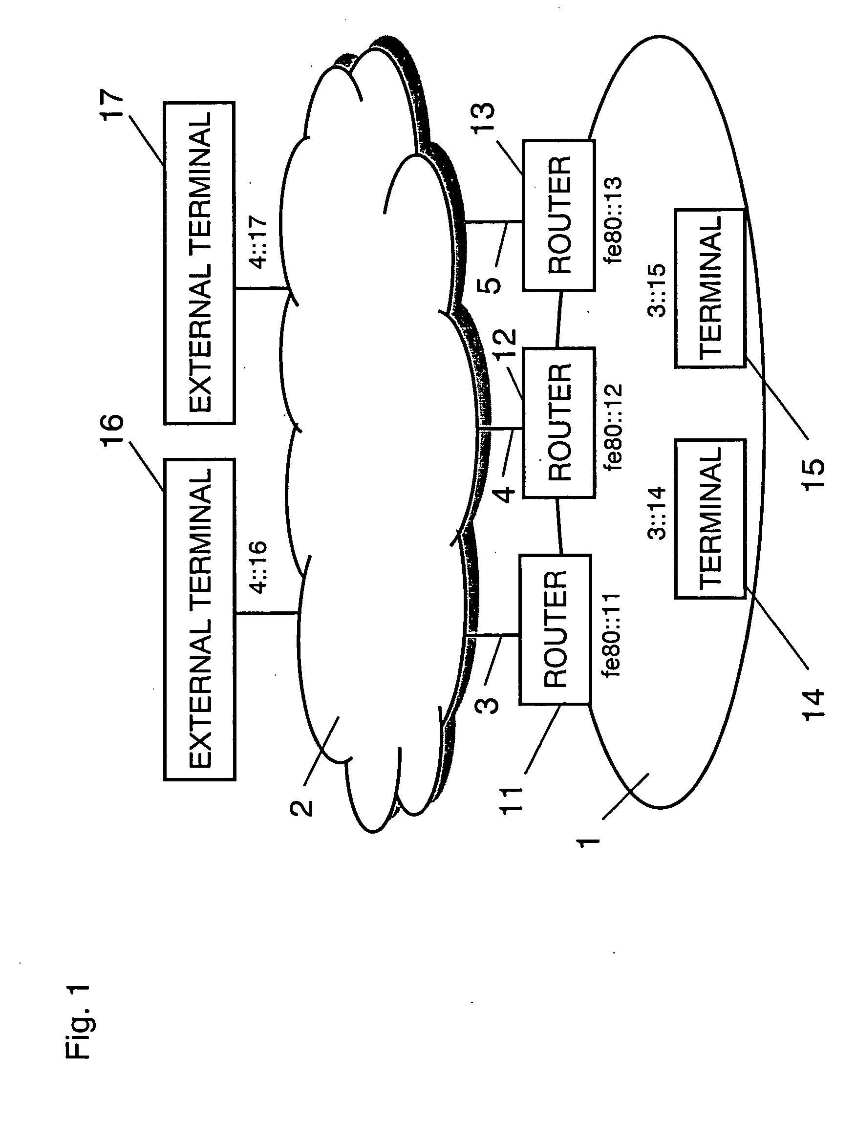
[0060]FIG. 1 is a diagram showing a constitution of a network in an embodiment of the invention.

[0061] In FIG. 1, routers 11, 12, and 13 relay communication between a LAN 1 and an external network 2 and include access interfaces with a third-generation cellular phone (band: 364 kbps, packet charge) 3, a PHS (band: 64 kbps, flat rate) 4, and a wireless LAN (band: 5 Mbps, flat rate) 5. Terminals 14 and 15 belong to the LAN 1. External terminals 16 and 17 are connected to the external network 2. The routers 11 to 13 include LAN interfaces as well as the access interfaces and are connected to the terminals 14 and 15 having the same LAN interface.

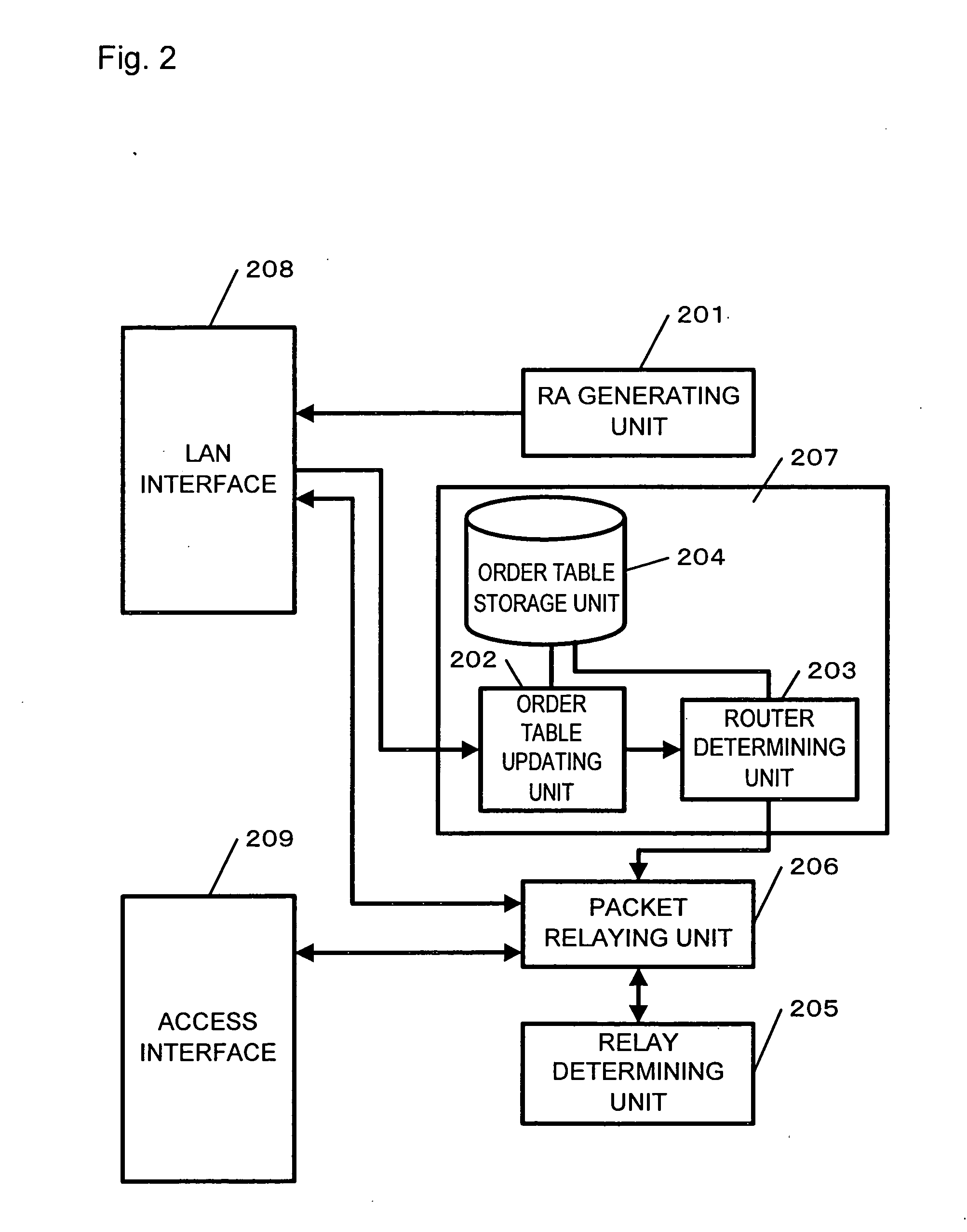
[0062]FIG. 2 is a block diagram showing a constitution of the routers 11, 12, and 13 in this embodiment. In FIG. 2, a LAN interface 208 performs physical layer processing and data link layer processing for communication with the terminals 14 and 15 and other routers connected to the LAN 1. An access interface 209 performs physical layer proces...

second embodiment

[0128] A network constitution in this embodiment is different from the first embodiment shown in FIG. 1 in that routers to which the router selecting method in the invention can be applied and those which cannot be unaware (hereinafter referred to as unaware routers) are present in the same LAN. In this embodiment, an order table is formed only including routers to which the router selecting method in the invention can be applied (hereinafter referred to as applicable routers). The unaware routers are stored separately. A data packet is transferred to the unaware routers only when the relay router cannot be selected from among the applicable routers.

[0129] Differences from the first embodiment will be explained concerning the constitution and operation of a router in this embodiment.

[0130]FIG. 18 is a block diagram showing the constitution of the router in this embodiment.

[0131] The constitution of the router is different from the constitution of the router in the first embodimen...

third embodiment

[0151] In a router selecting method in this embodiment, a router does not transmit a redirection message to a terminal which transmitted the packet while the router is transferring a packet to another router and transmits the redirection message for the first time when a router that shall perform relay processing is decided. FIG. 21 is a block diagram showing the constitution of a router in this embodiment. The constitution of this router is different from the constitution of the router in the first embodiment shown in FIG. 2 in that the router has a header information storage unit 211, a relay report transferring unit 212, and a relay report constructing unit 213.

[0152] The header information storage unit 211 stores header information. If the relay determining unit 205 determines that the router shall not relay the data packet and if this is the original router to transfer the packet, the header information storage unit 211 stores header information of the data packet.

[0153] The ...


PUM


Abstract

A router includes a multicast packet transmitting unit that multicasts the identifier of the router periodically, a relay determining unit that determines whether a received data packet should be relayed to a router in another segment, an order determining unit that determines, on the basis of information included in multicast packets from the other routers, the router to which the data packet shall be transferred, and a packet relaying unit that, when the data packet is not relayed, notifies the transmission source which transmitted the packet as to the router selected by the order determining unit to be the relay destination and then transfers the data packet to the selected router. A router suitable for relaying the packet is thus selected. Since switching of the relay router may be performed by following the router redirection message, it is unnecessary to add a new function to a terminal.

Description

TECHNICAL FIELD [0001] The present invention relates to a router in a local area network (LAN) in which two or more router apparatuses having a function of connecting to an external network are present, and, in particular, to a router selecting method and a router apparatus for determining a router suited to a specific packet flow. BACKGROUND ART [0002] Conventionally, as the router selecting method, there is the method described in “Virtual Router Redundancy Protocol” (S. Knight, et al.). [0003] In the method described in the literature, a set of routers called virtual routers share one IP address, one router serving as a master router operates as the default router of the LAN, and the other routers are put on standby as backup routers. Priorities are set for the respective routers. [0004] If the master router can no longer operate as the default router of the LAN for some reason, a router having the highest priority among the backup routers starts operating as the master router. [...

Claims


Application Information

Patent Timeline
IPC IPC(8): H04L12/26H04L12/56H04J3/26H04L12/46H04L12/66H04L45/02H04L45/16
CPCH04L45/00H04L45/125H04L45/16H04L45/306H04L45/58H04L45/586H04L45/60H04L45/06H04L45/56
Inventor KUMAZAWA, MASAYUKIMATSUMOTO, TAISUKEIKEDA, SHINKICHIKOBAYASHI, HIROKAZUFUNABIKI, MAKOTOKAWAHARA, TOYOKI
Owner APPLE INC
Learn More