Percutaneous endoscopic access tools for the spinal epidural space and related methods of treatment

Inactive Publication Date: 2006-09-14
THE BOARD OF TRUSTEES OF THE LELAND STANFORD JUNIOR UNIV +1
View PDF46 Cites 279 Cited by
  • Summary
  • Abstract
  • Description
  • Claims
  • Application Information

AI Technical Summary

Benefits of technology

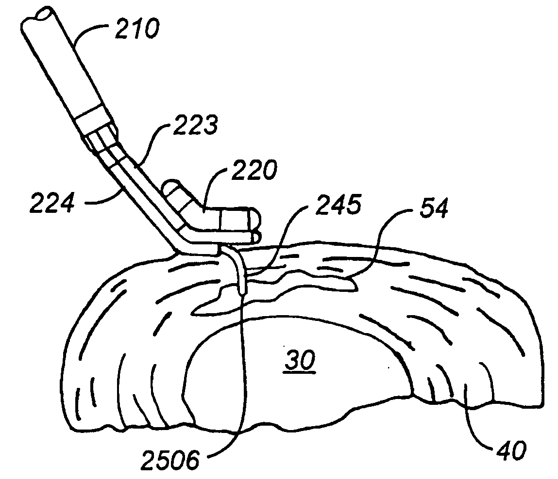
[0011] In one embodiment of the present invention, there is provided a method for providing therapy to the spine by percutaneously introducing an instrument into a body; steering the instrument to a position adjacent the outer surface of the spinal dura matter using visualization information provided by the instrument; displacing the spinal dura matter with a portion of the instrument to enlarge the spinal epidural space; and advancing the instrument into the enlarged spinal epidural space. In a further aspect, the method may include placing the instrument in a position to provide therapy within the spinal region. In another aspect, the visualization information is provided from an image generated by a sensor located on the instrument. In another aspect, the sensor utilizes light to generate the image, the light has a wavelength between 1.5 to 15 microns, and/or the light has a wavelength suited to infrared endoscopy in the spinal region. In another aspect, the sensor utilizes acoustic energy to generate the image, the sensor utilizes an electrical characteristic to generate the image and/or the sensor distinguishes the type of tissue adjacent the sensor. In another aspect, displacing the spinal dura matter comprises displacing without piercing the spinal dura matter. In still another aspect, the method includes displacing the spinal dura matter with a portion of the instrument to enlarge the spinal epidural space is performed using an atraumatic tip of the instrument. In still another aspect, the method may include displa

Problems solved by technology

The resulting pressure on these nerves often leads to pain, weakness and/or numbness in the lower extremities, upper extremities, or neck region.
Additionally, once injured, the healing capacity of the annulus fibrosis is limited.
However, the annulus fibrosis never returns to its original strength.
In many cases, the annulus fibrosis never closes becoming highly susceptible to re-herniation or nucleus leakage.
This “roll” shape causes a reduction in mechanical stiffness of the joint which may result in joint instability.
A bulging nucleus pulposis results in pain, weakness, and numbness in the area of the body associated with the particular nerve.
However, these devices provide little in the form of tactile sensation for the surgeon or allow the surgeon to atraumatically manipulate surrounding tissue.
In general, these conventional systems rely on external visualization for the approach to the disc and thus lack any sort of real time, on-board visualization capabilities.
Furthermore, accurately diagnosing back pai

Method used


Image

  • Percutaneous endoscopic access tools for the spinal epidural space and related methods of treatment
  • Percutaneous endoscopic access tools for the spinal epidural space and related methods of treatment
  • Percutaneous endoscopic access tools for the spinal epidural space and related methods of treatment

Examples


Embodiment Construction

[0049]FIG. 2A illustrates an embodiment of a spinal access device 110 of the present invention. The spinal access device 110 includes a pair of working channels 113, 114 in a distal end 112. Additionally, the spinal access device 110 has a visualization port 115 covered by a shaped atraumatic tip 118. The visualization port 115 is used by illumination, visualization and / or imaging components to provide direct visualization capabilities for the spinal access device. In one aspect, the visualization port 115 may house one or more conventional illumination, visualization, analytical and / or imaging components used to illuminate, visualize, analyze or image the surrounding anatomical environment. The spinal access device 110 is illustrated within a conventional trocar or introducer 102. The trocar 102 has a distal tip 104, a proximal end 106 and a lumen 108 there through. The trocar 102 and lumen 108 are selected and sized to receive the spinal access device 110.

[0050] In one embodiment...


PUM


Abstract

Several alternative spinal access devices are described. A number of alternative methods for performing therapies in the spinal region using the described spinal access devices are also described.

Description

CROSS-REFERENCE TO RELATED APPLICATIONS [0001] This application is a continuation-in-part of U.S. patent application Ser. No. 11 / 078,691 filed on Mar. 11, 2005, incorporated herein in its entirety.FIELD OF THE INVENTION [0002] The present invention relates to methods and apparatuses for providing percutaneous access to portions of the spine, delivering devices and agents via the access as well as performing various therapeutic treatments to the spine and surrounding tissue. More particularly, devices and methods described herein may be used for example to perform annulus repair, herniated disc repair, denervation of neurological tissue, dispensing pharmacological agents and / or cell or tissue therapy agents, diagnosing disc degeneration and bony degeneration; nucleus decompression; as well as disc augmentation. BACKGROUND OF THE INVENTION [0003]FIG. 1A is a posterior lateral view of two vertebral bodies 20 separated by an intervertebral disc 10. The intervertebral disc 10 is a cushio...

Claims


Application Information

Patent Timeline
IPC IPC(8): A61B17/88A61F2/44A61F2/46
CPCA61B17/00234A61B17/0218A61B17/320036A61B17/3421A61B18/1477A61B18/22A61B2017/003A61B2017/00557A61B2017/22038A61B2017/3445A61B2018/1425A61B2018/143A61B2018/1475A61B2019/5206A61B2019/5217A61F2/4611A61F2002/4627A61B2090/3614A61B2090/306A61B18/1482
Inventor KIM, DANIEL H.CHIN, ROY
Owner THE BOARD OF TRUSTEES OF THE LELAND STANFORD JUNIOR UNIV
Why Eureka
Try Eureka