[0008] Especially during operation in push mode, that is, when the takeoff rpm's are higher than the drive rpm's, this situation has disadvantageous effects as soon as the bridging clutch is to be closed for the purpose of taking
advantage of the braking action of the drive to reduce or avoid a long period of efficiency-impairing slippage or to prevent an unbraked acceleration of the drive upon a sudden transition from push mode to pull mode. The following unpleasant effect then occurs:
[0009] As a result of the filling of the hydrodynamic clutch device with clutch fluid, this fluid pushes its way radially outward under the effect of
centrifugal force, and ideally we can assume a pressure of “zero” at the center of rotation of the clutch device. As the distance from the center of rotation increases, however, the pressure values increase monotonically, near-maximum values being reached in the area of the radial extension of the bridging clutch, which is usually located in the radially outer area of the device. The increase in these pressure values during operation in push mode is more pronounced in the hydrodynamic circuit than in the pressure space, because the clutch fluid in the pressure space rotates essentially at the same speed as the clutch housing, whereas in the hydrodynamic circuit it rotates at the higher takeoff-side speed of the
turbine wheel. Under consideration of the boundary condition that, when the bridging clutch is open, the pressure conditions within the area of the radial extension of the bridging clutch are equalized between the hydrodynamic circuit and in the pressure space, the difference between the pressure-increase curves on the two sides of the piston have the effect that the course of the
pressure increase in the pressure space—starting from the area of the radial extension of the bridging clutch and leading radially inward from there—undergoes less of a pressure drop than the course of the
pressure increase on the opposite side of the piston, that is, in the hydrodynamic circuit. The consequence of this is that the pressure in the part of the pressure space radially inside the bridging clutch is higher than that in the hydrodynamic circuit, as a result of which the piston is held stably in the released position. If, under these conditions, an actuating command is given to close the bridging clutch, a
positive pressure must first be built up in the hydrodynamic circuit which significantly exceeds the pressure in the pressure space. There is a therefore a considerable
delay in the closing of the bridging clutch.
[0010] As soon as the piston of the bridging clutch starts moving toward its engaged position after the necessary high
positive pressure has been built up in the hydrodynamic circuit, the connection between the hydrodynamic circuit and the pressure space becomes smaller and thus acts increasingly as a
throttle, which has the effect of lowering the pressure in the pressure space below that present in the hydrodynamic circuit and thus ultimately causes the sign of the
axial force acting on the piston to reverse. Although the piston would thus now be able to shift into its engaged position by itself, the high
positive pressure built up in the hydrodynamic circuit—which had no effect previously while the piston was not moving—now goes suddenly into effect, exerting a strong
axial force which accelerates the engaging movement of the piston, so that the piston travels at a very
high velocity over the last part of its engaging
stroke and thus enters into working connection with the axially adjacent, drive-side component of the clutch housing, such as, for example, a housing cover, in a very abrupt manner. As a result, the speed difference previously existing between the drive and the takeoff disappears within a very short time. In a vehicle traveling in push mode, this process is felt as an unpleasantly hard torque surge, which detracts from the comfort of the vehicle's passengers and also reduces the service life of the clutch device itself. SUMMARY OF THE INVENTION
[0011] The invention is based on the task of designing a hydrodynamic clutch device with a bridging clutch which can be closed without causing a surge in the torque even during operation in push mode.
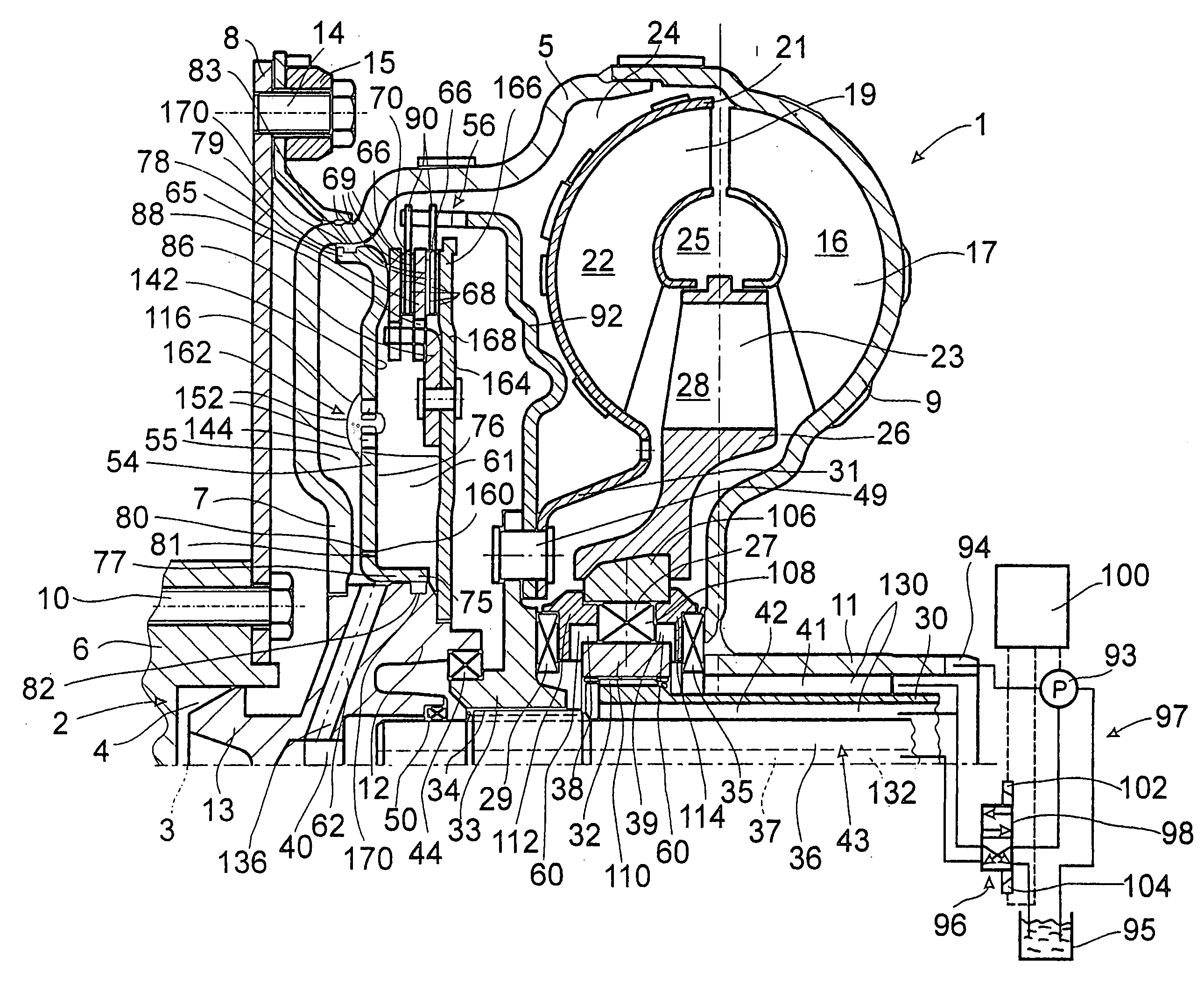
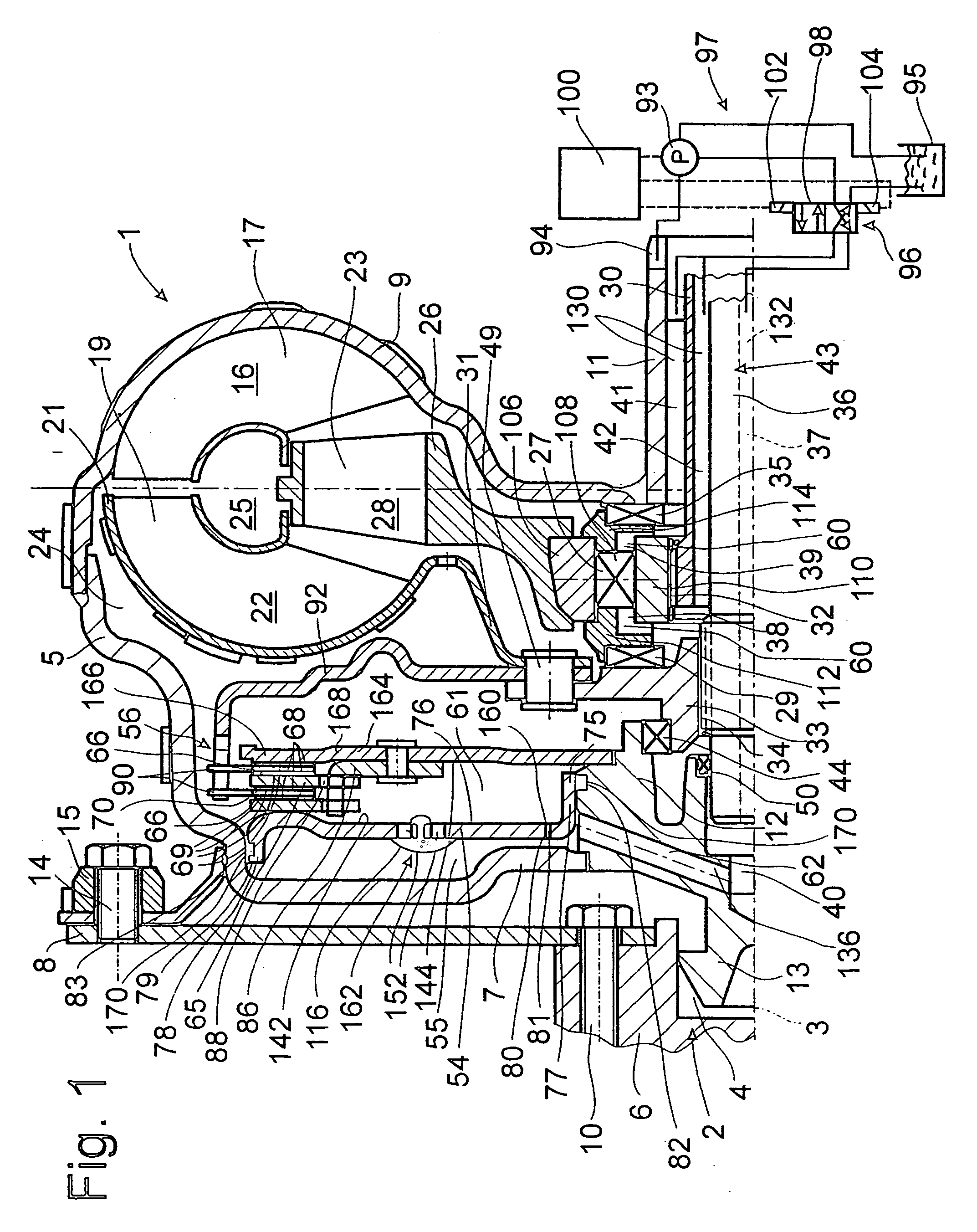
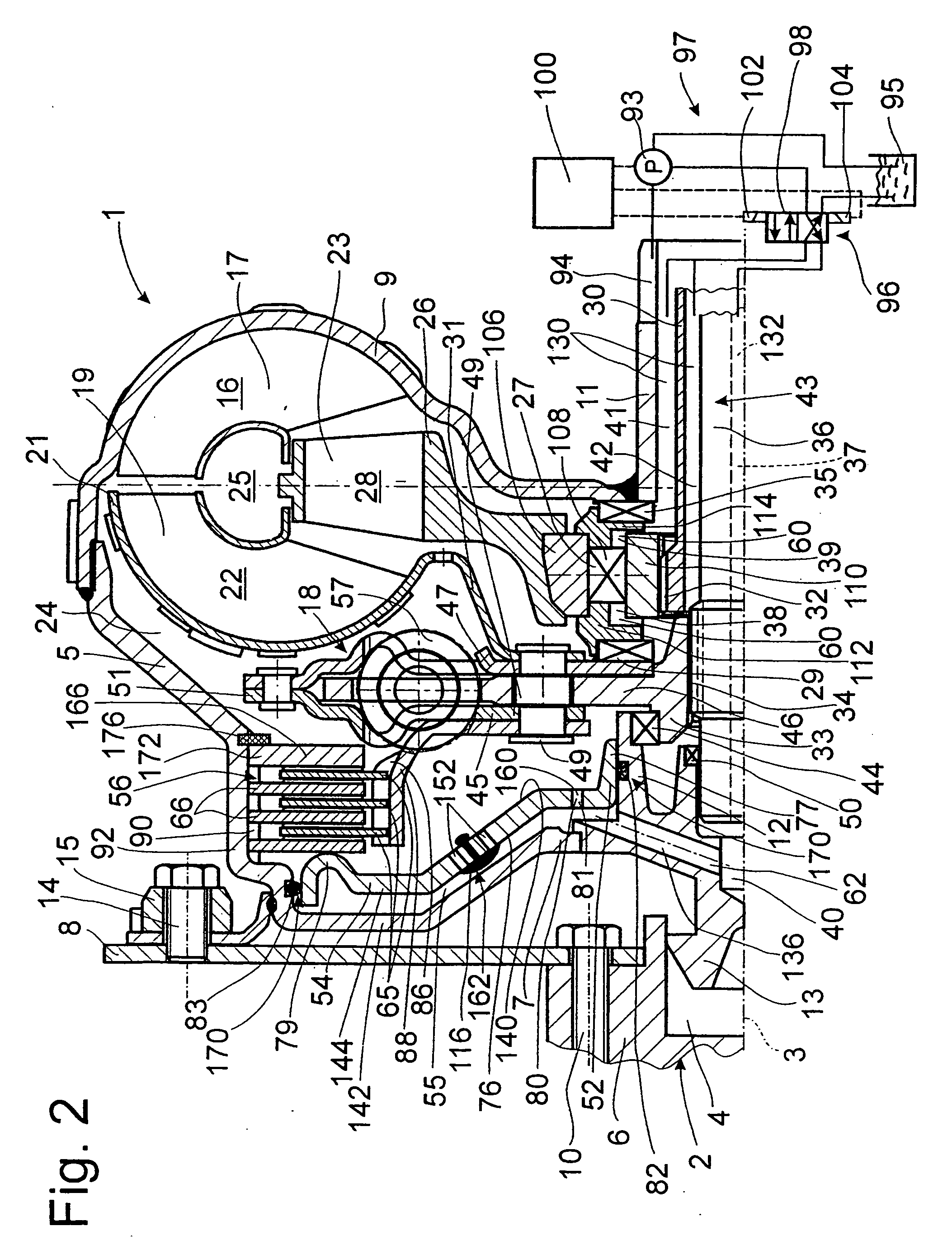
[0012] According to the invention, the bridging clutch is accommodated in the hydrodynamic circuit and a sealing site is installed between the circuit and the pressure space in the form of a seal assigned to the piston of the bridging clutch, with the result that when the piston travels within its
range of movement between the released position and the engaged position, there is no change in the working direction of the pressure-induced
axial force being exerted on the piston. This advantageous effect is achieved for the reason that, when the bridging clutch is accommodated in the hydrodynamic circuit, there is no pressure drop at the bridging clutch even when the piston is displaced, regardless of whether the bridging clutch ends up being open or closed. Simultaneously, the sealing site between the two pressure areas required for the realization of a two-line
system, namely, between the hydrodynamic circuit and the pressure space, is provided not in the otherwise conventional friction area of the bridging clutch but rather at a different point in the hydrodynamic clutch device, namely, in the area of the piston. The sealing site between the hydrodynamic circuit and the pressure space thus becomes independent of the position which the piston may occupy relative to the components of the bridging clutch such as the plates.
[0013] It is true that, as a result of this design of the hydrodynamic clutch device, pressure-increase curves which rise in an essentially monotonic manner between the axis of rotation and the area of the radial extension of the bridging clutch develop both in the hydrodynamic circuit and in the pressure space. Because of the higher rotational speed of the
turbine wheel on the takeoff side in push mode, the
pressure curve in the hydrodynamic circuit rises more quickly than that in the pressure space on the opposite side of the piston. Because of the special arrangement of the sealing site between the hydrodynamic circuit and the pressure space, however, achieved by assigning the seal to the piston, these two pressure-increase curves will not interact in such as way as to create any pressure-induced effects which could influence the shifting behavior of the bridging clutch, namely, by allowing the direction of the axial force acting on the piston to reverse. The pressure supply of the hydrodynamic circuit is sufficient to keep the piston in its released position as long as it is supposed to remain there. To engage the piston, the filling of the pressure space is sufficient to give the piston the tendency to engage as soon as the pressure in the pressure circuit connected to the pressure supply is turned off and thus the pressure supply to both the hydrodynamic circuit and to the pressure space is briefly interrupted. Thus—as soon as the pressure space is connected to the pressure supply again—even a very slight positive pressure in the pressure space versus the hydrodynamic circuit is sufficient to move the piston and thus to control with great sensitivity the closing behavior of the bridging clutch. Upon reaching its engaged position, the piston thus makes soft contact with the corresponding drive-side component of the clutch housing such as the housing cover without producing any surge in the torque surge. To this extent the passengers of a vehicle equipped with this type of clutch device will enjoy a very comfortable ride.

