Projection display apparatus using liquid cooling and air cooling
a technology of projection display and liquid cooling, which is applied in the direction of projectors, color television details, instruments, etc., can solve the problems of increasing maintenance costs, reducing the life of the product, and serious loss of functions, so as to reduce noise, reduce maintenance costs, and prolong life time
- Summary
- Abstract
- Description
- Claims
- Application Information
AI Technical Summary
Benefits of technology
Problems solved by technology
Method used
Image
Examples
first embodiment
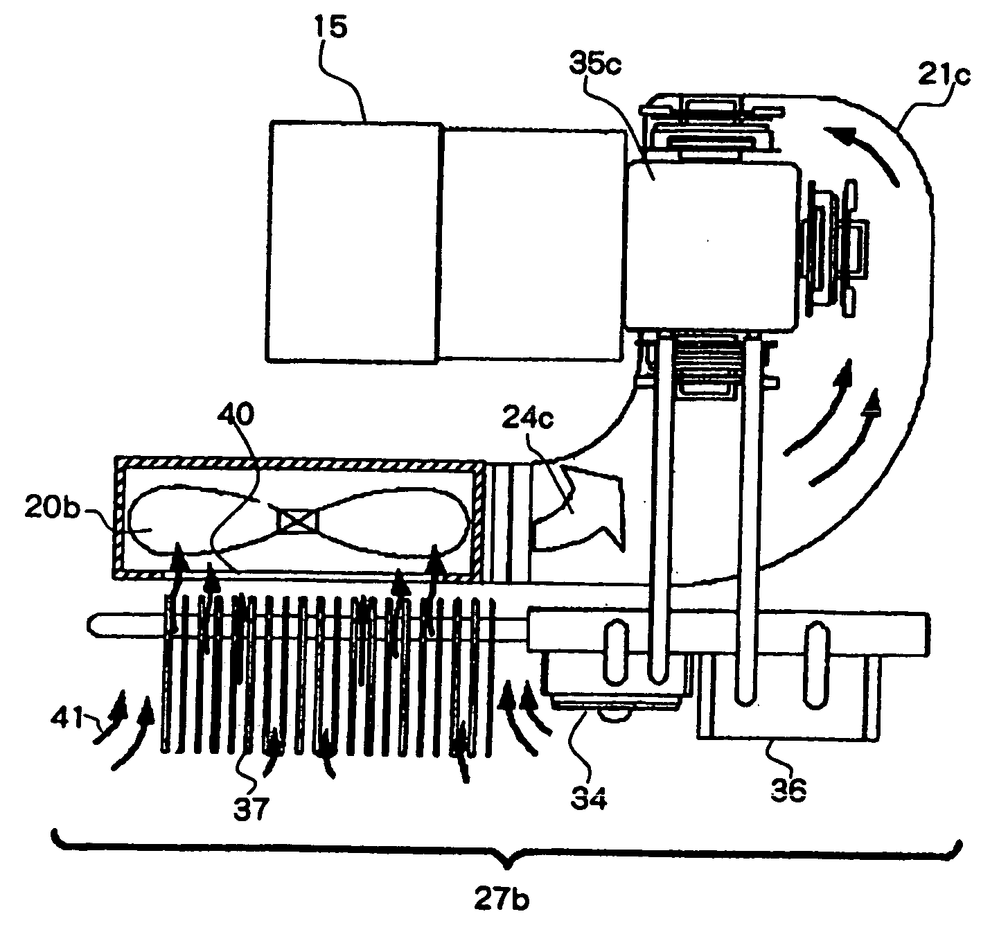
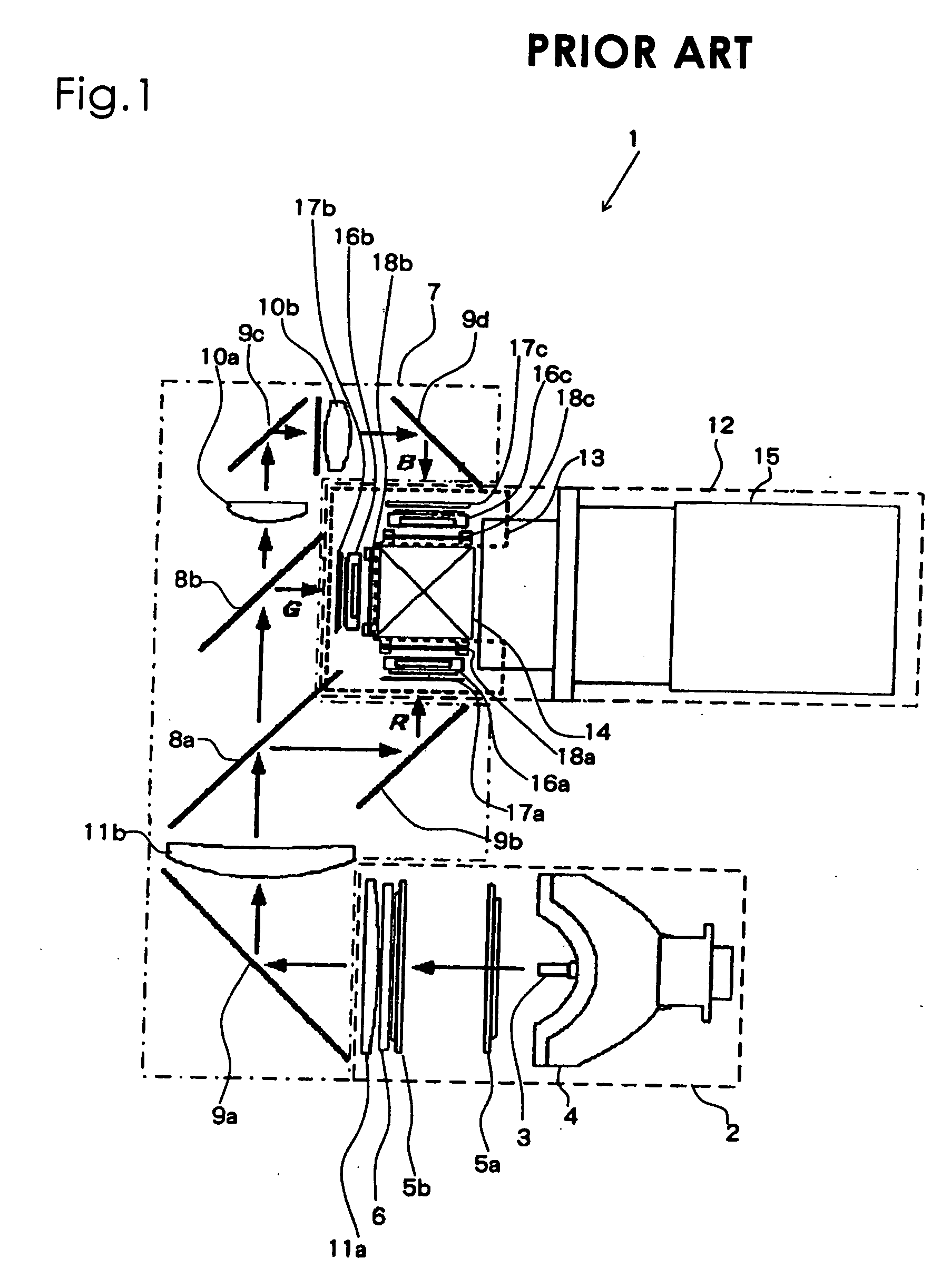
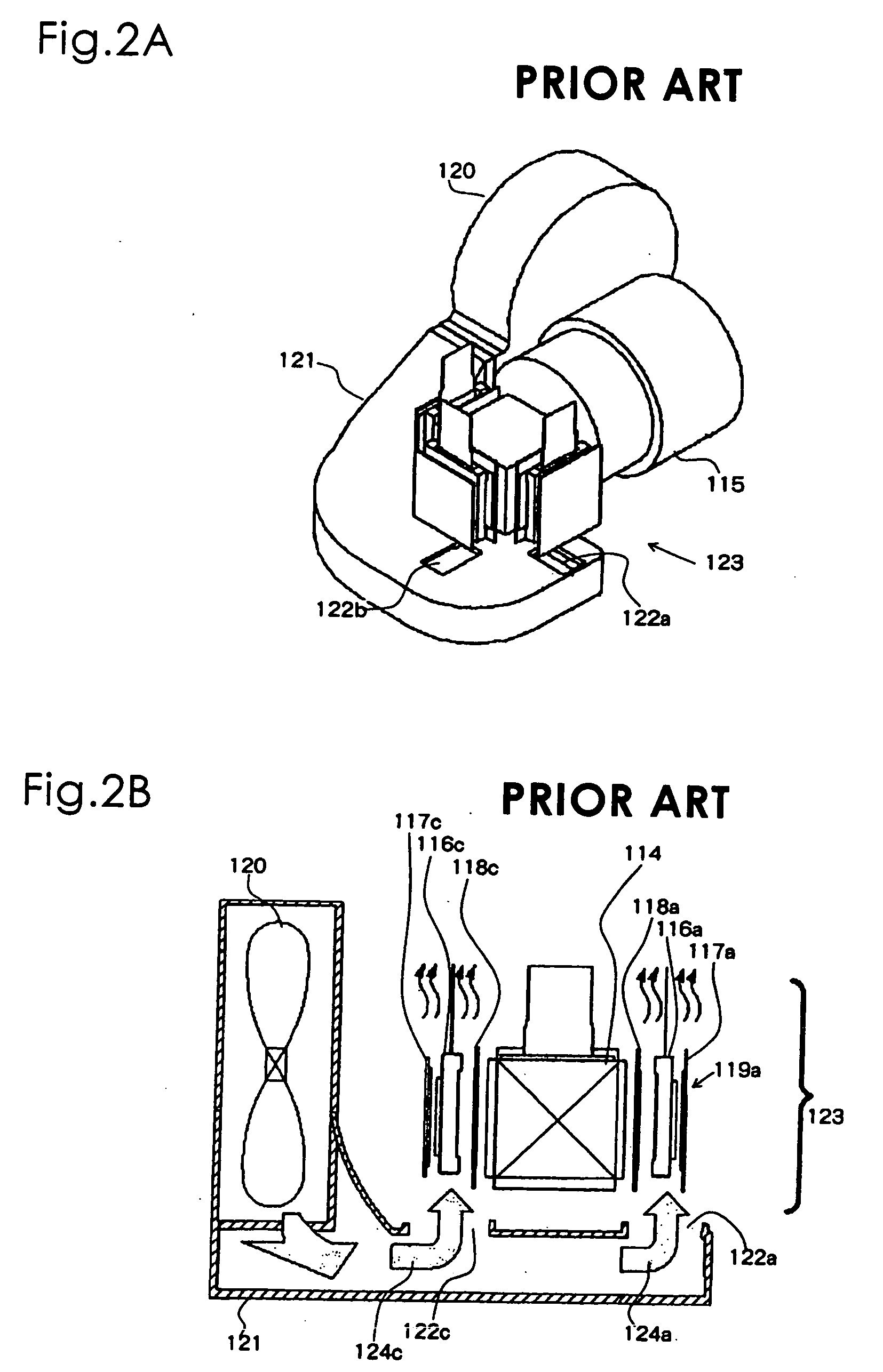
[0058] With reference to the drawings, detailed explanations are given about a mechanism for cooling liquid crystal units according to the present invention. The same reference numerals are given to the elements and the structures that have the same functions as conventional mechanisms for cooling liquid crystal units that are explained with reference to FIGS. 1 and 2. In this specification, as described above, the combination of an incident side polarizing plate, an emitting side polarizing plate, and a liquid crystal panel is called liquid crystal unit 19. The combination of three liquid crystal units, a color combining prism, and holding members is called liquid crystal unit assembly 23.
[0059] Referring to FIGS. 7 and 8, mechanism for cooling liquid crystal units 25a according to the first embodiment consists of liquid crystal unit assembly 23a, air cooling module 26a, and liquid cooling module 27a which functions as a heat exchanger.
[0060] Liquid crystal unit assembly 23a, simi...
third embodiment
[0092] In such an arrangement of the radiator for the heat exchanger a fan is not required for heat radiation from the radiator, leading to a reduction in the cost of the overall cooling system and in noise. In addition, the size of the apparatus can be also reduced due to the reduction in the space necessary for mounting of the apparatus.
[0093] In the first, second, and third embodiments, a liquid cooling module is used as a heat exchanger. However, it is obvious that the same effect can be obtained by other types of heat exchangers, such as a heat pipe or a vapor chamber.
[0094] Finally, differences between the method for cooling liquid crystal units of prior arts, which are explained with reference to FIGS. 3 to 6, and the method according to the present invention are explained.
[0095] The first embodiment of the present invention is similar to the prior arts shown in FIGS. 3 and 4 in that heat that is generated in emitting side polarizing plates 18 is transmitted to holders 28 ...
second embodiment
[0098] In the prior arts shown in FIGS. 3, 4, upper holder 228 for color combining prism 214 is provided with heat radiating fins 242 in order to enhance heat radiating efficiency. On the other hand, air cooling fins (heat sink) are attached to the lower holder. Further, since the fin portion is engaged in the duct of the air cooling module, which co-operates with the liquid cooling module, sufficient heat radiation by the fins can be obtained due to the sufficient level of forced convection heat transfer. The present invention is also different from the prior arts shown in FIGS. 3, 4 in these respects.
[0099] Additionally, in the first and second embodiments, the air cooling module, which co-operates with the liquid cooling module, is configured such that cooling air is concentrated on the incident side polarizing plates and the liquid crystal panels. Thus, the present invention is different from the prior arts in that the cooling margin can be easily ensured.
[0100] In the second ...
PUM
 Abstract
Description
Claims
Application Information
 - R&D
- Intellectual Property
- Life Sciences
- Materials
- Tech Scout
- Unparalleled Data Quality
- Higher Quality Content
- 60% Fewer Hallucinations
Browse by: Latest US Patents, China's latest patents, Technical Efficacy Thesaurus, Application Domain, Technology Topic, Popular Technical Reports.
© 2025 PatSnap. All rights reserved.Legal|Privacy policy|Modern Slavery Act Transparency Statement|Sitemap|About US| Contact US: help@patsnap.com


