Transmitter with an envelope tracking power amplifier utilizing digital predistortion of the signal envelope

a technology of power amplifier and signal envelope, which is applied in the direction of digital transmission, secret communication, baseband system details, etc., can solve the problems of rf power amplification, low rf power amplification, and low amplifier efficiency

Inactive Publication Date: 2006-09-21
ANDREW LLC
View PDF17 Cites 48 Cited by
  • Summary
  • Abstract
  • Description
  • Claims
  • Application Information

AI Technical Summary

Problems solved by technology

RF power amplification techniques, and particularly RF power amplification techniques used for wireless applications, have inherent drawbacks to which the industry continues to direct its efforts.
Amplifier efficiency, which is generally defined as the level of RF power that may be achieved at the output signal compared to the power that is input into the overall amplification process, is conventionally somewhat low in wireless applications.
Another drawback in RF power amplification, which must be addressed and taken into account with any methods for improving efficiency, is signal distortion.
Non-linearities of the amplifier, as well as other factors, contribute to the distortion.
However, while envelope-tracking techniques improve efficiency, various current implementations of those envelope tracking techniques have various drawbacks.
Such drawbacks are associated with the ability of the system to respond to the signal envelope.
However, since there are imperfections or non-linearities in the tracking behavior of the power supply, the resulting output voltage from the power supply is only a crude approximation of the envelope levels actually required for the power amplifier.
If, for a particular envelope peak, the power supply output is not sufficient for the amplifier requirements, the distortion produced by the amplifier could be greatly increased, even after predistortion of the input signal has been taken into account to address other inherent non-linearities in the power amplifier.

Method used


Image

  • Transmitter with an envelope tracking power amplifier utilizing digital predistortion of the signal envelope
  • Transmitter with an envelope tracking power amplifier utilizing digital predistortion of the signal envelope
  • Transmitter with an envelope tracking power amplifier utilizing digital predistortion of the signal envelope

Examples


Embodiment Construction

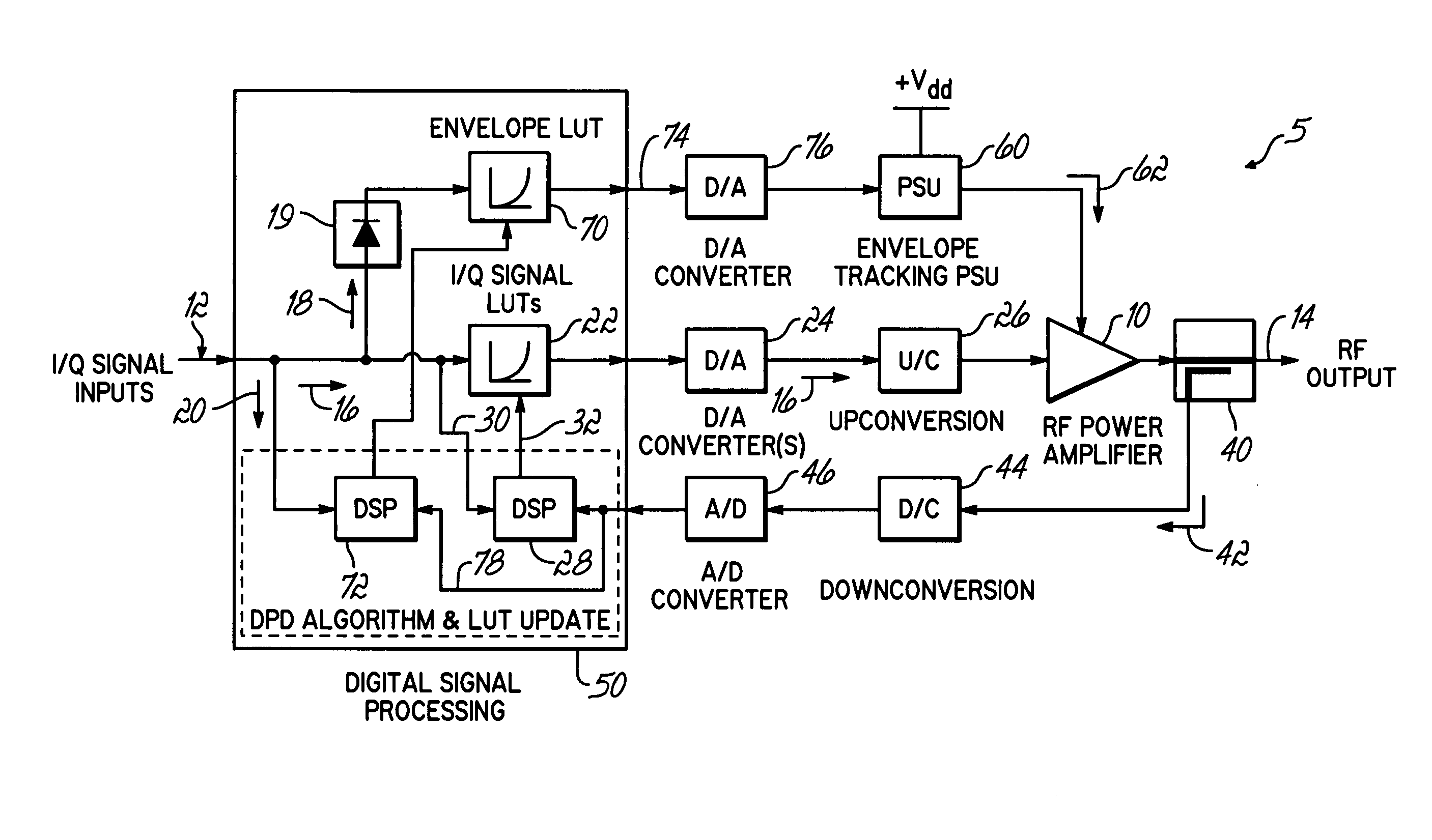
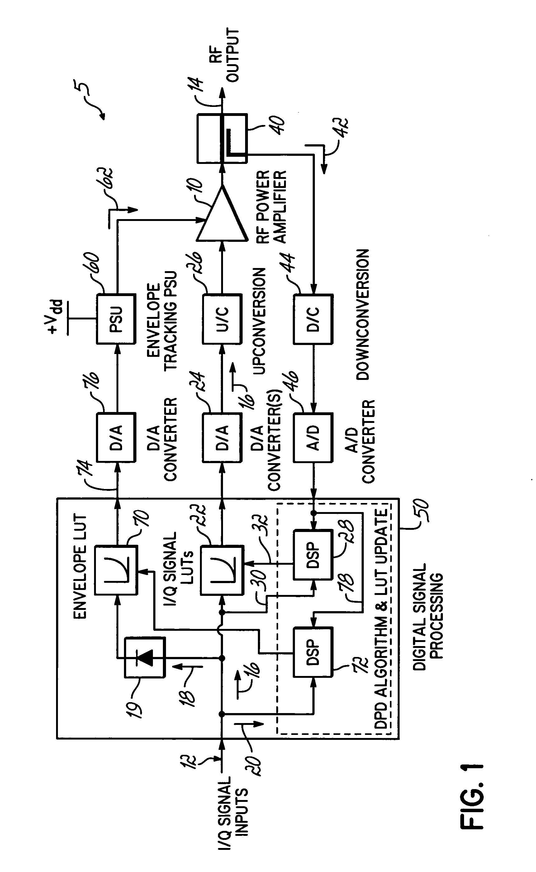
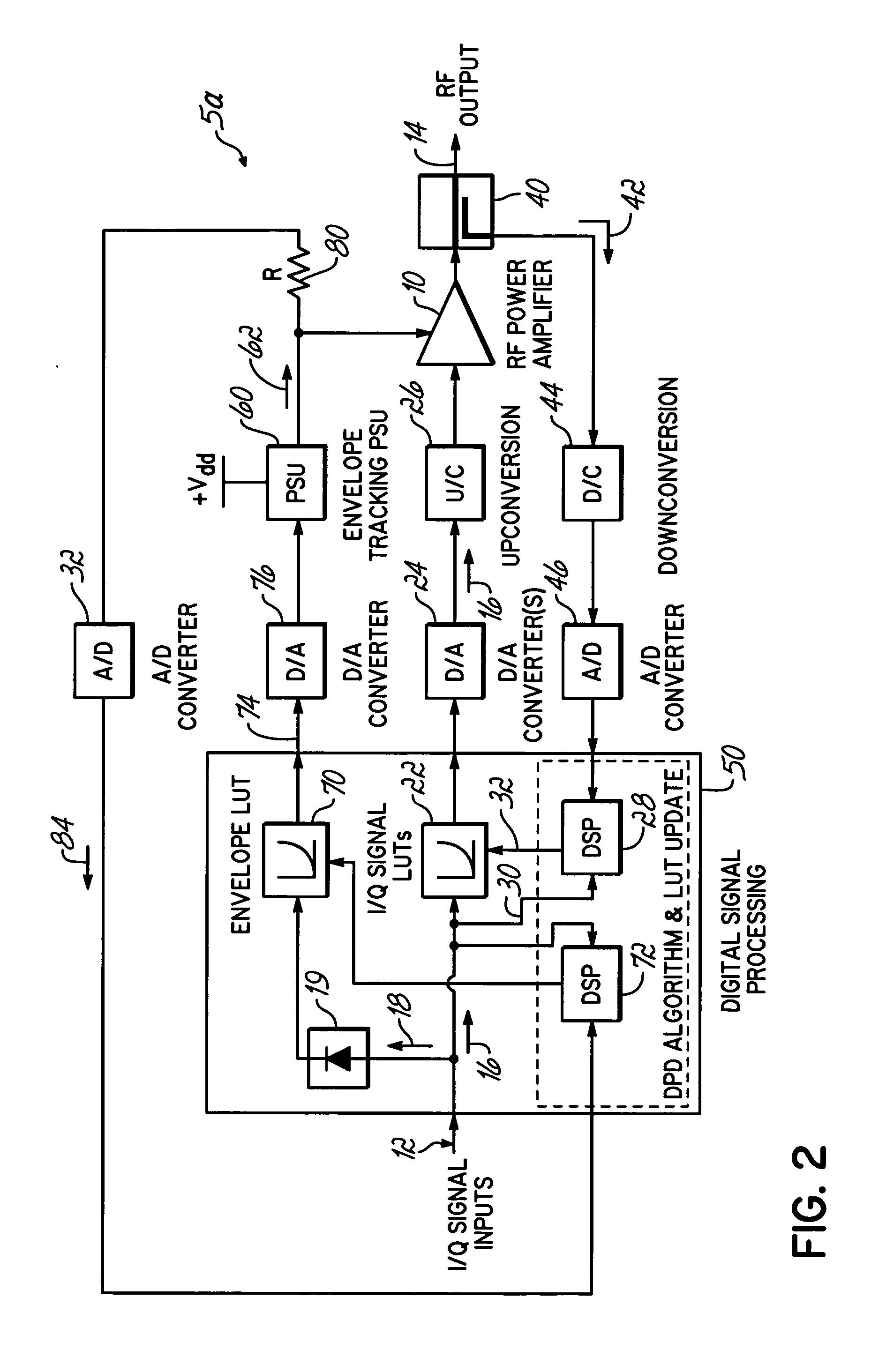
[0015] The present invention addresses the above-noted drawbacks in the prior art, and specifically addresses the non-linearities and other characteristics of a power supply utilizing envelope tracking in a power amplifier system. Specifically, the present invention addresses imperfections in the tracking behavior of the power supply by predistorting the envelope signal provided to the tracking power supply to ensure that it accurately reflects the true status of the input signal envelope at a given instant in time. For example, the predistortion of the envelope signal in an envelope-tracking power amplifier is utilized to address various non-linearities and slew-rate limitations in the tracking power supply that feeds the drain or drains of the main RF amplifier devices.

[0016] In another aspect of the invention, the predistortion provides over-compensation of the envelope characteristics to deliberately create a small amount of “head room” in the power that is supplied to the ampl...


PUM


Abstract

A transmitter comprises an amplifier operable for receiving an input signal and amplifying the input signal to produce an output signal. A power supply is coupled to the amplifier for supplying power to the amplifier, the power supply operable for tracking the input signal and varying the level of power supplied to the amplifier in response to variation of the input signal. A predistortion circuit is coupled to the power supply, the predistortion circuit operable for receiving the input signal and predistorting the input signal to the power supply for addressing input signal tracking capabilities of the power supply.

Description

BACKGROUND OF THE INVENTION [0001] In wireless communication applications, such as cellular phone services or other wireless services, amplifiers are used to provide the desired signal coverage for the particular wireless application. For example, radio frequency (RF) power amplifiers are used for boosting the level of an RF signal prior to transmission of that signal. RF power amplification techniques, and particularly RF power amplification techniques used for wireless applications, have inherent drawbacks to which the industry continues to direct its efforts. Specifically, in developing an RF transmission system, considerable attention is given to amplifier efficiency and signal distortion of the amplified signal. [0002] Amplifier efficiency, which is generally defined as the level of RF power that may be achieved at the output signal compared to the power that is input into the overall amplification process, is conventionally somewhat low in wireless applications. Therefore, con...

Claims


Application Information

Patent Timeline
Patent Type & Authority Applications(United States)
IPC IPC(8): H04L25/49
CPCH03F1/0222H03F2200/102
Inventor KENINGTON, PETER BLAKEBOROUGH
Owner ANDREW LLC
Why Eureka
Try Eureka