Cooling system for motor vehicles and method for controlling at least one air mass flow through a radiator

a cooling system and motor vehicle technology, applied in the direction of ducting arrangement, lighting and heating apparatus, heating types, etc., can solve the problems of limiting free space, reducing cooling efficiency, and limiting the case in which the air-conveying system is not possible, so as to achieve rapid heat-up of the cooling medium flowing through the radiator. , the effect of minimal cooling efficiency

Inactive Publication Date: 2006-09-21
ILLINOIS TOOL WORKS INC +1
View PDF32 Cites 63 Cited by
  • Summary
  • Abstract
  • Description
  • Claims
  • Application Information

AI Technical Summary

Benefits of technology

[0022] To reach the objective, we also propose a method for controlling at least one air mass flow through the radiator of a motor vehicle during the various operating phases of the motor vehicle, said method having the features indicated in claim 36. According to this method, during the first, ram pressure-dominated operating phase of the motor vehicle, namely during a forward movement of the motor vehicle at a sufficiently high speed at which a desired ram air pressure is created at the font end of the motor vehicle, a first free air stream is supplied to the radiator through at least one air inlet provided in the outer wall of the motor vehicle, said air stream flowing through the radiator from the front end thereof. By “free air stream” is meant that said stream is created exclusively as a result of the ram pressure prevailing at the front end. During this operating phase, any required air mass flow through the cooling module or through the radiator can be made available. Moreover, by said method it is possible that during the second operating phase of the motor vehicle, namely ...

Problems solved by technology

The drawback of the known cooling system is that under operating conditions in which the air mass flow through the cooling module is created by ram pressure at the front end of the motor vehicle, the cover of the fan cap and the fan hub act as resistances increasing the pressure loss caused by the cooling module.
This results in nonuniform flow through the radiator which also affects the heat exchanger disposed ahead of it and, i...

Method used


Image

  • Cooling system for motor vehicles and method for controlling at least one air mass flow through a radiator
  • Cooling system for motor vehicles and method for controlling at least one air mass flow through a radiator
  • Cooling system for motor vehicles and method for controlling at least one air mass flow through a radiator

Examples


second embodiment

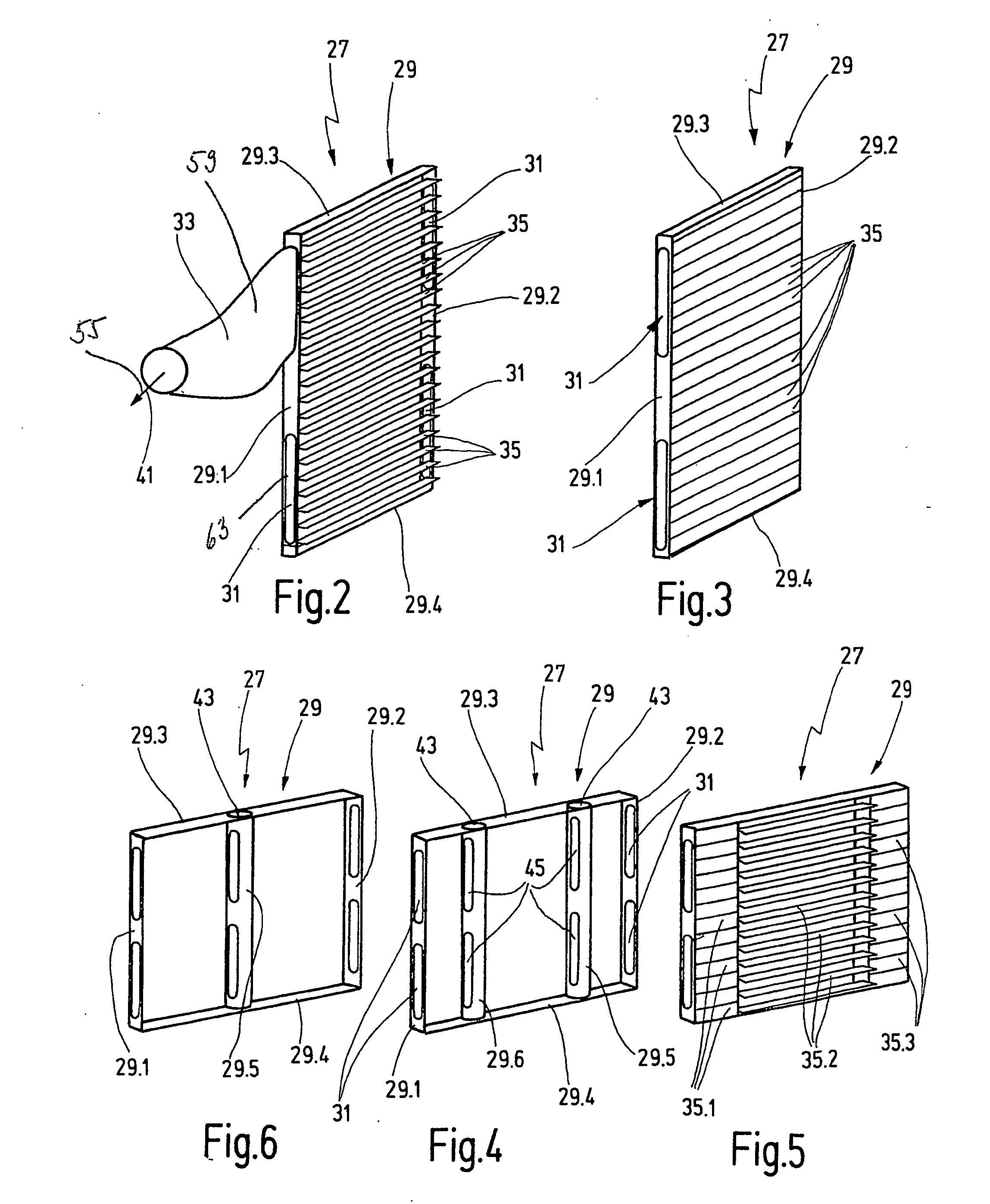
[0061]FIG. 4 depicts cover 27, with flaps 35 not showing, and which differs from cover 27 described with the aid of FIGS. 1 to 3 particularly in that additional frame parts 29.5 and 29.6 are provided between frame parts 29.1 and 29.2 that form the side walls of cover 27, said additional frame parts being disposed parallel to frame parts 29.1 and 29.2. As can be seen from FIG. 5, a first number of flaps 35.1 is held in swivelable manner at frame parts 29.1 and 29.6, a second number of flaps 35.2 is held at frame parts 29.6 and 29.5, and a third number of flaps 35.3 is held at frame parts 29.5 and 29.2. Flaps 35.1 to 35.3, each allotted to a partial region of the radiator surface are swivelable independently of each other so that only parts of cover 27 can be closed and the air flow path is only partly blocked. It is thus possible for the air mass flow over the cooling module to consist of a combination of ram pressure flow and suction via flow-through openings 31.

[0062] In FIG. 5, fl...

third embodiment

[0069]FIG. 8 shows a schematic representation of radiator 19 and cover 27 in cross-section. Parts that have already been described with the aid of the foregoing figures are indicated by the same reference numerals. Radiator 19 has a wedge-shaped contour with the tip of the wedge pointing in the direction of forward movement 8 of motor vehicle 3. Frame 29 of cover 27 that is disposed on the radiator back side 25 is adapted to the shape of radiator 19 and it, too, is wedge-shaped. This is achieved by disposing lateral frame parts 29.1 and 29.2 at an appropriate angle. This design, too, has only a small structural depth. The orientation of the radiator and of the cover can be chosen so that during forward movement of the motor vehicle the tip of the wedge is directed in the direction opposite to that of forward movement, namely in a direction that is exactly opposite to that shown for the embodiment represented in FIG. 8.

[0070] Flaps 35 of cover 27 shown in FIGS. 7 and 8 can be swivele...


PUM


Abstract

Cooling system for motor vehicles with at least one radiator to which in a first operating phase, particularly in the ram pressure phase, a first air stream can be supplied via a first air flow path and which in an alternative or simultaneous second operating phase, particularly during fan operation, can be supplied by means of at least one air-conveying device, with a second air stream flowing along a second air flow path. Among other things, it is also provided that at least in some regions the two air flow paths are oriented at an angle to each other so that the air-conveying device is disposed outside or essentially outside the first air flow path. The invention also related to a corresponding method.

Description

CROSS-REFERENCE TO RELATED APPLICATIONS [0001] This application is a National Stage of International Application No. PCT / DE02 / 02827, filed Jul. 26, 2002 which claims benefit of German patent application number 10137717.7, filed Aug. 1, 2001.BACKGROUND AND SUMMARY OF THE INVENTION [0002] The invention relates to a cooling system for motor vehicles with at least one radiator. The invention also relates to a method for controlling at least one air mass flow through the radiator of a motor vehicle during different operating phases of the vehicle. [0003] In motor vehicles, for example passenger cars or trucks, the cooling of the liquids and gases used therein is carried out by means of appropriate heat exchangers, for example intercoolers, coolant coolers or condensers, which are located at the front end of the motor vehicle, often in a modular unit, namely one behind the other as seen in the direction of forward movement of the motor vehicle. [0004] EP 0 487 098 B1 discloses a cooling s...

Claims


Application Information

Patent Timeline
IPC IPC(8): F24F13/04B60K11/04B60K11/08F01P7/10
CPCB60K11/08B60K11/085F01P7/10Y02T10/88
Inventor BROTZ, FRIEDRICHPANTOW, EBERHARDUHL, BERNHARD
Owner ILLINOIS TOOL WORKS INC
Why Eureka
Try Eureka