
System and method for attaching a vein, an artery, or a tube in a vascular environment

a technology of vascular environment and system, applied in the field of cardiac and vascular surgery, can solve the problems of cumbersome bypass instruments, large amount of estimating or guessing, and many holes in the aortic wall that are simply incorrect, and achieve the effects of enhancing the bypass operation, superior control, management and performance, and high precision

Inactive Publication Date: 2006-09-21
CASTLEWOOD SURGICAL
View PDF67 Cites 14 Cited by
  • Summary
  • Abstract
  • Description
  • Claims
  • Application Information

AI Technical Summary

Benefits of technology

[0007] From the foregoing, it may be appreciated by those skilled in the art that a need has arisen for an improved bypass instrument for achieving superior control, management, and performance during a bypass procedure. In accordance with an embodiment of the present invention, a device, a system, and a method for enhancing a bypass operation are provided that includes a flexible, highly precise, easy-to-use device, which substantially eliminates or greatly reduces disadvantages and problems associated with conventional bypass equipment and instruments.
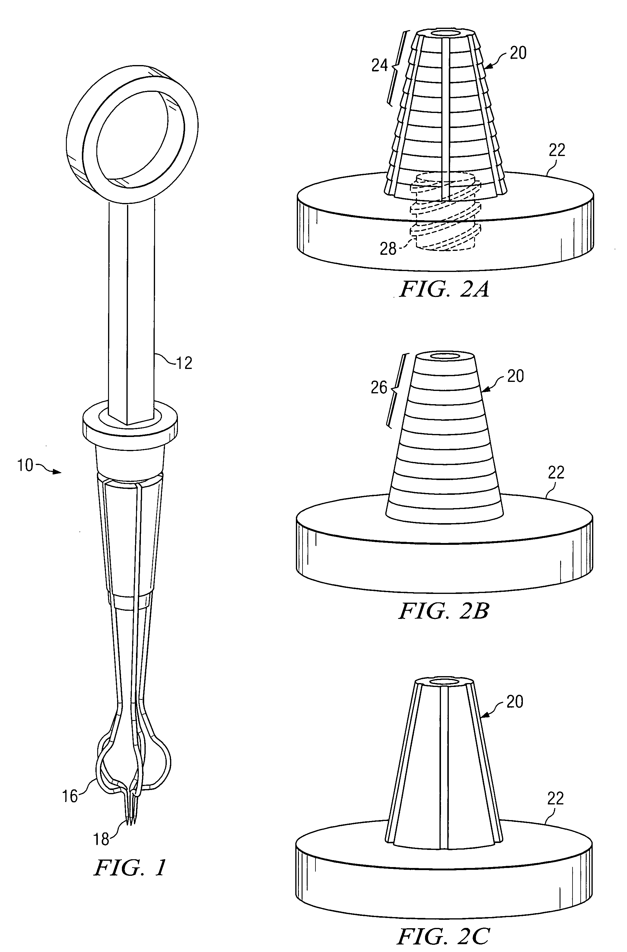
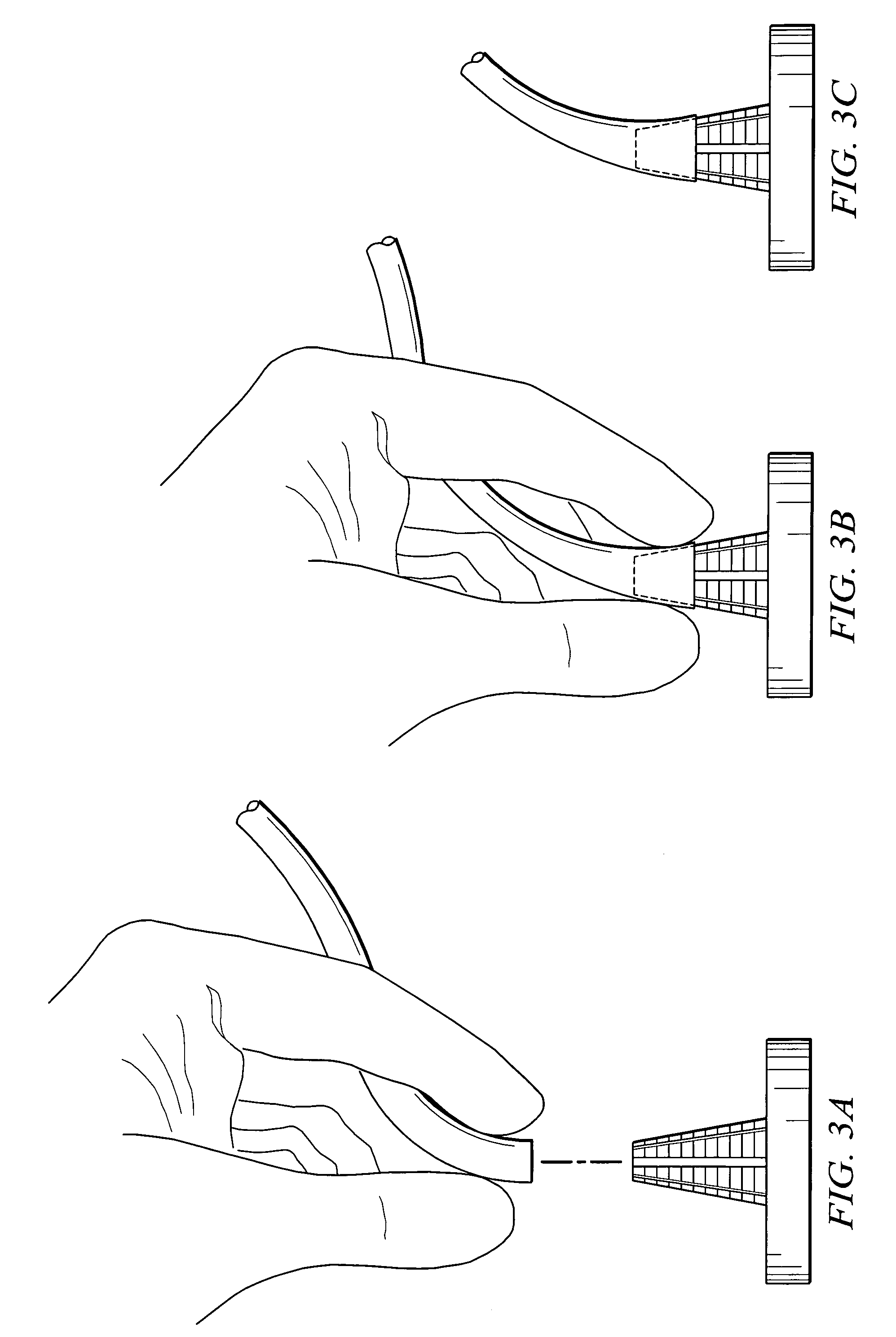
[0009] Certain embodiments of the present invention may provide a number of technical advantages. For example, according to one embodiment of the present invention, an architecture and a process are provided that offer a flexible system, which can easily accommodate a vein of any size. The present system can include a simple loading procedure that offers exceptional flexibility and adaptability for a physician. In addition, the present invention offers increased accuracy for a surgeon who must make a precise incision in the aortic wall. In one embodiment, graduations may be provided on a stand (which stabilizes the vein) in order to clearly elucidate the exact size of the harvested vein and, therefore, dictate the size of the hole to be made in the aortic wall. In addition, the procedure associated with the present invention is minimally invasive, whereby clamping of the aorta (which can be problematic) is no longer necessary.
[0010] The present invention also offers a device that avoids any injury or damage to the harvested vein. The integrity of the vein is maintained during the tendered process, as the physician can suitably position and then transport the vein in a safe and reliable manner. Additionally, any violation of the aorta is effectively avoided in the operation of the present invention. Moreover, the present invention may involve suturing operations, which can be beneficial in a number of respects. For example, suturing may be preferred because it offers minimal stress to a somewhat fluid system, which responds negatively to sheer, torque, and other external forces. Thus, flexibility is incorporated into the device, as it readily allows for suturing and clipping operations to be performed. Note that suturing operations offer a consistent and an effective protocol for a surgeon, who is accustomed to performing such familiar tasks. Note also that the design of the present invention facilitates the suturing process, as outlined below. Additional advantages are described herein with reference to corresponding FIGURES.

Problems solved by technology

One issue associated with any bypass operation relates to flexibility.
In addition, there is a significant amount of estimating or guesswork that normally transpires during a given bypass operation.
This may result in making holes in the aortic wall that are simply incorrect.
Moreover, many bypass instruments are cumbersome, difficult to manipulate, potentially harmful to patients, and clumsy or awkward in many situations.
Their deficiencies create a significant burden on the physician, who is already being taxed by a number of arduous tasks.
In addition, many current devices are unacceptable because they violate the interior of the aorta, which (in turn) can cause trauma and inflammation issues.
Accordingly, the ability to provide an effective medical instrument that properly accounts for the aforementioned problems presents a significant challenge for component manufactures, system designers, and physicians alike.

Method used


Image

  • System and method for attaching a vein, an artery, or a tube in a vascular environment
  • System and method for attaching a vein, an artery, or a tube in a vascular environment
  • System and method for attaching a vein, an artery, or a tube in a vascular environment

Examples


Embodiment Construction

[0020]FIG. 1 is a simplified schematic diagram of a device 10, which may be used during a bypass operation. Device may include a handle 12 and one or more legs 16, which include one or more tips 18. By pushing or by pulling on handle 12, one or more of legs 16 may extend, separate, and / or open in order to grasp or to initiate contact with any suitable object.

[0021] Tips 18, which are sharp and which are provided on each of legs 16, may be used to pierce a vein being used in a given bypass procedure. Tips 18 allow for a precise removal of the vein from a loading structure (e.g. a stand or a base), which is described in greater detail below with reference to FIGS. 2A-C. In particular, legs 16 may be controlled such that they are operable to lift a vein directly from the loading structure.

[0022] Legs 16 may be constructed of any suitable material (e.g. steel, titanium, plastic, etc.) and be provided in any appropriate configuration or orientation. In one embodiment, five legs 16 are ...


PUM


Abstract

A device for assisting in a vascular procedure is provided that includes a handle and one or more legs that are operable to move in response to a force being applied to the handle. The legs are operable to extend and to contract in order to manipulate a conduit. In a more particular embodiment, the device can be used in conjunction with a stand operable to receive the conduit such that the conduit can be removed from the stand by the device. The stand may include one or more graduations that indicate the size of the conduit once it is positioned on the stand.

Description

TECHNICAL FIELD OF THE INVENTION [0001] This invention relates in general to the field of cardiac and vascular surgery and, more particularly, to a process, a system, and a method for attaching a vein, an artery, or a tube in a vascular environment. BACKGROUND OF THE INVENTION [0002] The treatment of vascular diseases has grown exponentially in terms of sophistication and diversity. In particular, coronary artery bypass graft (CABG) surgery has become routine in most cardio-thoracic practices. Its popularity is due, in part, to its tremendous success rate and its ability to offer extraordinary benefits to a patient. [0003] CABG surgery restores blood flow to heart tissue that has been deprived of blood because of coronary artery disease. During bypass surgery, a new graft vessel, which will subsequently carry oxygenated blood around the blockage in a coronary artery, is surgically removed from another location in the body. The harvested graft vessel is a healthy artery or vein taken...

Claims


Application Information

Patent Timeline
Patent Type & Authority Applications(United States)
IPC IPC(8): A61M29/00
CPCA61B17/0469A61B17/0625A61B17/0644A61B17/068A61B17/11A61B17/1152A61B2017/061A61B2017/0647A61B2017/0649A61B2017/1135A61M25/02A61M2025/0286
Inventor HAMMAN, BARON L.
Owner CASTLEWOOD SURGICAL
Learn More