
Optical skin germicidal device and method

a germicidal device and optical technology, applied in light therapy, radiation therapy, therapy, etc., can solve the problems of ineffectiveness, limited penetration of typical antibiotics through the skin, difficult treatment of non-vascular areas in the human body with limited blood flow, etc., and achieve the effect of safe and effective application of germicidal ultraviolet light to living tissu

Inactive Publication Date: 2006-09-21
RIDDELL ROBERT H
View PDF18 Cites 8 Cited by
  • Summary
  • Abstract
  • Description
  • Claims
  • Application Information

AI Technical Summary

Benefits of technology

[0007] It is an object of the present invention to provide a tool for safely and effective applying germicidal ultraviolet light to living tissue
[0008] It is another object to provide such a tool that allows the ultraviolet light to be applied relatively close to the infected issue thereby reducing damaging to the surrounding non-infective living tissue.
[0009] It is another object of the present invention to provide such a tool that is safe and easy to use.

Problems solved by technology

It is also well known that non-vascular areas in the human body with limited blood flow are difficult to treat with oral or IV or IM administered antibiotics.
If the infection site is below the skin, typical antibiotics have limited penetration through the skin and are generally, ineffective.
Because ultraviolet light does not substantially penetrate living tissue, heretofore, it has not be used to treat infections.
In addition, because ultraviolet light is widely known to cause optical damage, most medical and dental practitioners are reluctant to use it on their patients.

Method used


Image

  • Optical skin germicidal device and method
  • Optical skin germicidal device and method
  • Optical skin germicidal device and method

Examples


first embodiment

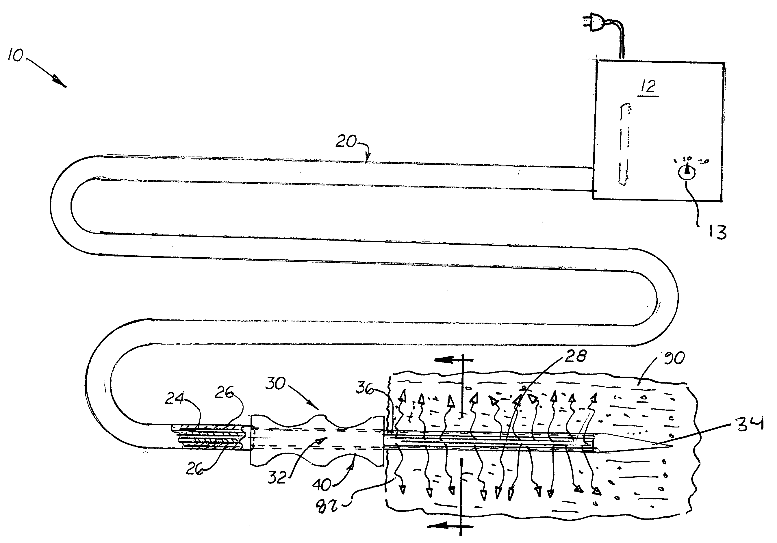
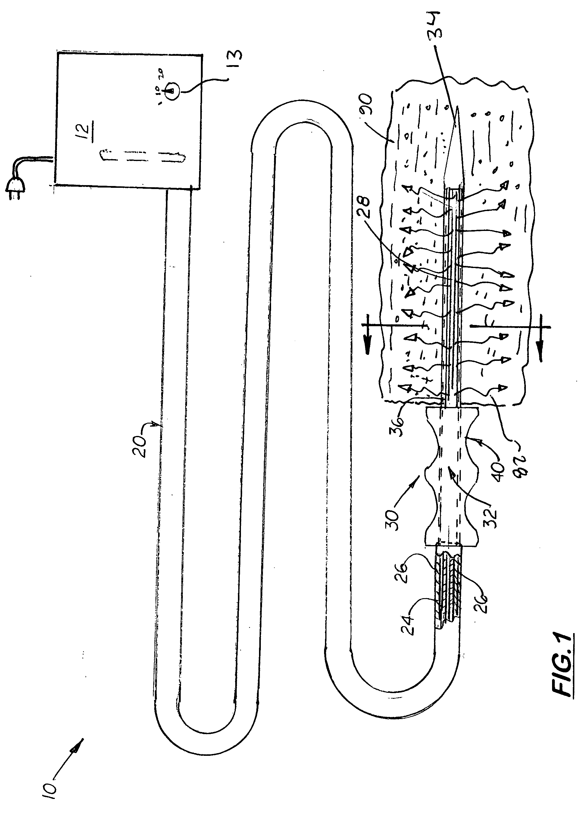
[0022] In the first embodiment shown in FIGS. 1 and 2, the needle 30 is a straight structure with a closed, sharp distal end 34 designed to penetrate living tissue 90. Attached to the proximal end 36 of the needle 30 is a large knob or handle 40 that the operator grabs to maneuver the needle 30 into and around the infected tissue 90. The proximal end 36 of the needle 30 extends slightly beyond the outer end of the handle 40 thereby allowing the optical fiber 20 to be easily inserted into the needle'center bore 32.

second embodiment

[0023] In a second embodiment, the tool 10 includes a curved needle, designated 30′, designed to be used to treat infected tissue 90 that cannot be accessed with the straight needle 30. The curve needle 30′ includes a closed sharp distal end 34′ and an optical handle 40′ formed at its proximal end 36′.

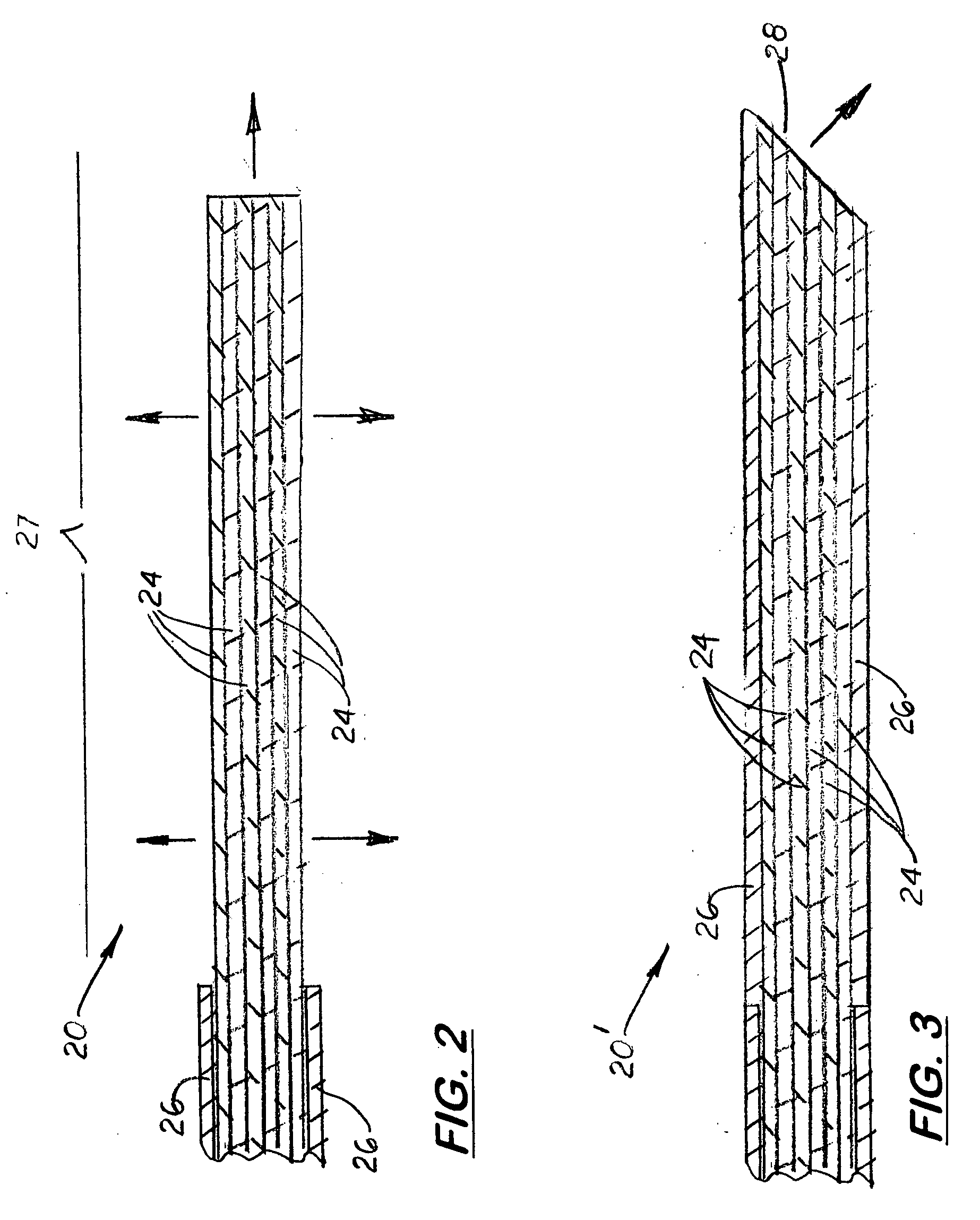
[0024] Formed on the surface of the needle 30, 30′ is at least one elongated slot 50 that allows rays of the germicidal light 82 from the distal section 27 or distal end 28 of the optical fiber 20, 20′ to exit the needle 30. The slot 50 may extend the entire length of the needle as shown in FIGS. 1 and 4 or be replaced with a plurality of longitudinally aligned, short slots 50′ as shown in FIG. 7. In both embodiments, the slot 50 or slots 50′ are sufficiently narrow so that the optical fiber 20 remains longitudinally aligned inside the needle 30 at all times. In the preferred embodiment, the optical fiber is approximately 1 / 16 inch in diameter and 36 to 48 inches in length. The needle ...


PUM


Abstract

An optical skin germicidal device and method that uses germicidal ultraviolet light to treat local infections. The device includes a germicidal light source connected to a flexible optical fiber and a hollow needle designed to receive the optical fiber. The optical fiber, which is designed to slide freely inside the needle, is covered with cladding except for the distal end or section that slides into the needle. Formed on the inside surface of the needle is an elongated slot that allows rays of optical light to exit the needle. The slot is sufficient in width so that the optical fiber remains at all times inside the curved needle. By moving the optical fiber along the needle, the tissue surround the inside surface of the needle adjacent to the slot may be treated with germicidal light. Using the device, a method of treatment is also provided.

Description

BACKGROUND OF THE INVENTION [0001] 1. Field of the Invention [0002] The invention disclosed herein pertains to sterilization devices and, more particularly to devices used to sterilize skin or living tissue using germicidal light. [0003] 2. Description of the Related Art [0004] Antibiotic resistant bacteria is a major concern in medicine and dentistry. Safe, effective alternative methods for treating bacteria infections that do not rely on antibiotics or other chemicals are needed. [0005] It is also well known that non-vascular areas in the human body with limited blood flow are difficult to treat with oral or IV or IM administered antibiotics. If the infection site is below the skin, typical antibiotics have limited penetration through the skin and are generally, ineffective. [0006] Because ultraviolet light does not substantially penetrate living tissue, heretofore, it has not be used to treat infections. In addition, because ultraviolet light is widely known to cause optical dama...

Claims


Application Information

Patent Timeline
Patent Type & Authority Applications(United States)
IPC IPC(8): A61N5/06
CPCA61N5/0601A61N5/0624A61N2005/0609A61N2005/063A61N2005/0644A61N2005/0661
Inventor RIDDELL, ROBERT H.
Owner RIDDELL ROBERT H
Learn More