Heating resistor type air flow rate measuring device and method of correcting measurement error

a technology of air flow rate and measuring device, which is applied in the direction of liquid/fluent solid measurement, volume/mass flow by differential pressure, instruments, etc., can solve the problems of air flow measurement error, measurement error, and measurement error

Inactive Publication Date: 2006-09-21
HITACHI LTD
View PDF7 Cites 5 Cited by
  • Summary
  • Abstract
  • Description
  • Claims
  • Application Information

AI Technical Summary

Benefits of technology

[0013] An object of the present invention is to correct pulsation-induced measurement errors of a heating resistor type air flow rate measuring device. More particularly, the present invention aims at providing a measurement error correction method and an instrument which are not affected by changes made to the intake system of a vehicle and external factors such as the atmospheric pressure and temperature. Another object of the present invention is to make it possible to estimate air flow measurement errors without using a low-pass filter, unlike in the method described in JP-A No. 536320 / 2004.

Problems solved by technology

If the intake air pulsation becomes larger than in the state shown in FIG. 11 causing a backflow to be generated in the intake pipe, the backflow causes measurement errors such that measured air flow rates are larger than actual air flow rates.
Delay in response of a heating resistor occurring when a pulsation flow is present also causes air flow measurement errors.
In reality, however, for the following reasons, it is difficult to eliminate delay in response of the output of a heating resistor.
Such measures, however, cause the bobbin-like part and the coating material to be subjected to heating by the heating wire.
Consequently, due to a thermal delay of the heating resistor, measurement delays occur with respect to true intake air pulsations.
Air flow rate values obtained by successively converting such delayed output voltage inevitably contain measurement errors.
Since the resonance frequency of a pipe line is dependent on the length of the pipe line, changing the length of the intake pipe or the position of a heating resistor in the intake pipe changes measurement errors of the heating resistor type air flow rate measuring device.
Consequently, measurement errors also change, and it may occur that air flow measurement errors are not properly corrected.

Method used


Image

  • Heating resistor type air flow rate measuring device and method of correcting measurement error
  • Heating resistor type air flow rate measuring device and method of correcting measurement error
  • Heating resistor type air flow rate measuring device and method of correcting measurement error

Examples


Embodiment Construction

[0035] A preferred mode for carrying out the present invention will be described with reference to an example of embodiment shown in drawings.

[0036] An embodiment of the present invention will be described in detail with reference to the accompanying drawings.

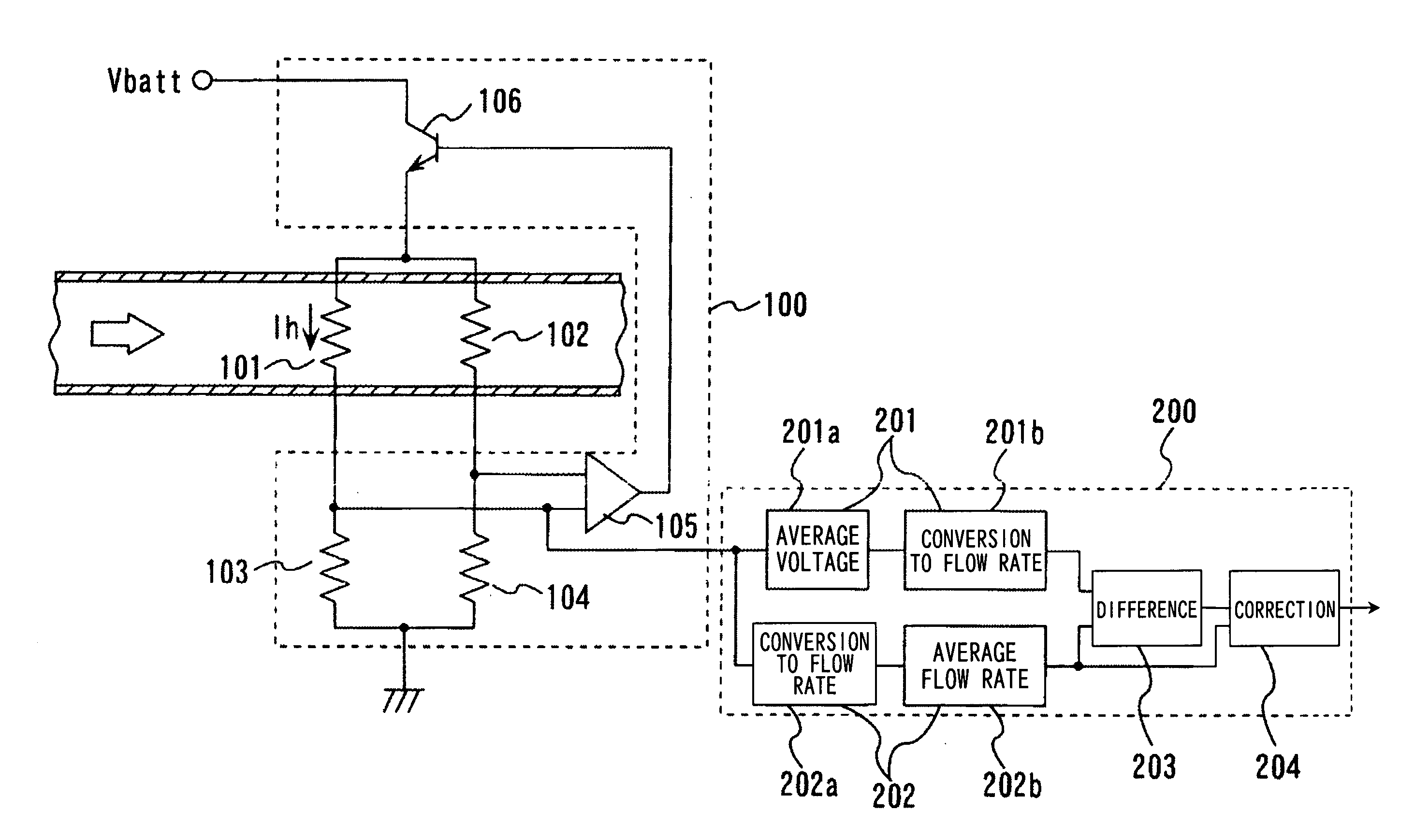
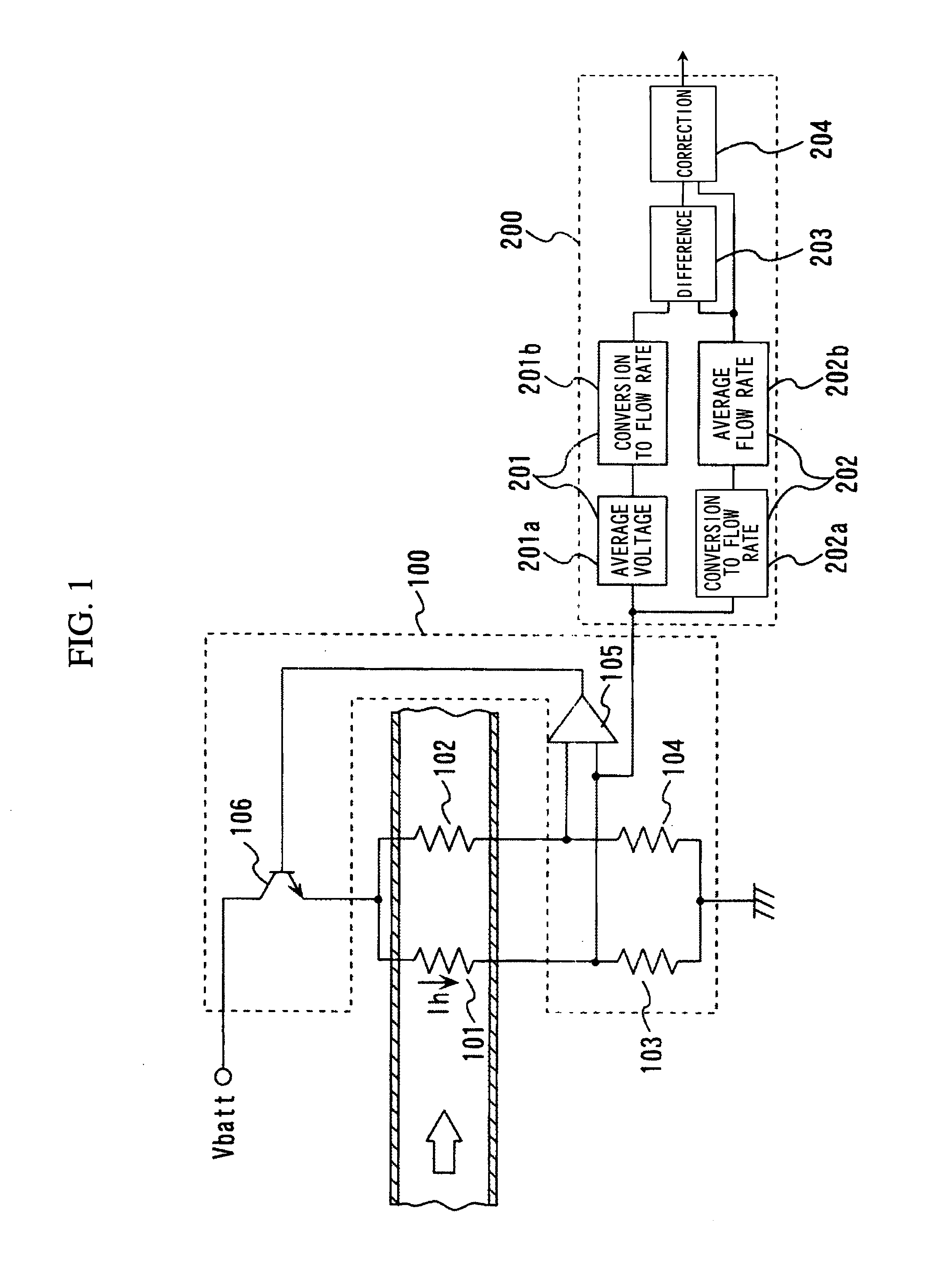
[0037]FIG. 1 is a schematic diagram of a heating resistor type air flow rate measuring device according to an embodiment of the present invention. Shown in the figure is an example of an instrument for measuring an air flow rate in an intake pipe of an automobile.

[0038] First, a principle of operation of the heating resistor type air flow rate measuring device will be described.

[0039] A sensing circuit (drive circuit) 100 of the heating resistor type air flow rate measuring device includes, broadly classified, a bridge circuit and a feedback circuit.

[0040] The bridge circuit includes a heating resistor 101 for measuring an intake air flow rate, a resistor 102 for intake air temperature compensation, and fixed resistors 103...


PUM


Abstract

A measurement error attributable to intake air pulsation of a heating resistor type air flow rate measuring device is corrected. A measurement error correction method not dependent on an intake system of a vehicle is provided. An output from a sensing circuit is sampled at prescribed time intervals. Output values thus sampled are successively converted to flow rate values. A first flow rate value is determined by averaging the flow rate values thus obtained in a prescribed amount of time. Separately, the output from the sensing circuit is averaged for a prescribed amount of time. The average output value thus obtained is converted to a second flow rate value. A correction value for correcting a measurement error is determined based on a difference between the first and second flow rate values.

Description

FIELD OF THE INVENTION [0001] The present invention relates to a device for measuring an air flow rate using a heating resistor, for example, a heating resistor type air flow rate measuring device suitable for measuring an intake air flow of an internal combustion engine of a vehicle. More particularly, it relates to correcting measurement errors attributable to an intake air pulsation flow. BACKGROUND OF THE INVENTION [0002] A heating resistor type air flow rate measuring device has been known as technology for measuring an air flow of an internal combustion engine. It makes use of a phenomenon that heat drawn from a heating resistor increases monotonically relative to an air flow rate. Since it can directly measure a mass flow rate, it is widely used as a flow meter in connection with vehicle fuel control. [0003] In a heating resistor type air flow rate measuring device, the output voltage of a sensing circuit varies nonlinearly with respect to the air flow rate. In an intake pipe...

Claims


Application Information

Patent Timeline
Patent Type & Authority Applications(United States)
IPC IPC(8): G01F25/00
CPCG01F1/69G01F1/6965G01F1/698G01F1/72G01F5/00
Inventor KOBAYASHI, CHIHIRO
Owner HITACHI LTD
Why Eureka
Try Eureka