Cogeneration system

a cogeneration system and engine technology, applied in the direction of machines/engines, mechanical equipment, greenhouse gas reduction, etc., can solve the problems of large amount of thermal energy and systems cannot be said to use thermal energy efficiently

Inactive Publication Date: 2006-09-28
SUGIOKA TETUO
View PDF2 Cites 34 Cited by
  • Summary
  • Abstract
  • Description
  • Claims
  • Application Information

AI Technical Summary

Benefits of technology

[0037] It is preferable that a constricting part is installed within the combustion chamber as means of accelerating the flow of exhaust gas therein against the heater.

Problems solved by technology

This structure wastes a large amount of the thermal energy generated by the thermal source, and therefore these cogeneration systems cannot be said to use thermal energy efficiently.

Method used


Image

  • Cogeneration system
  • Cogeneration system
  • Cogeneration system

Examples


Embodiment Construction

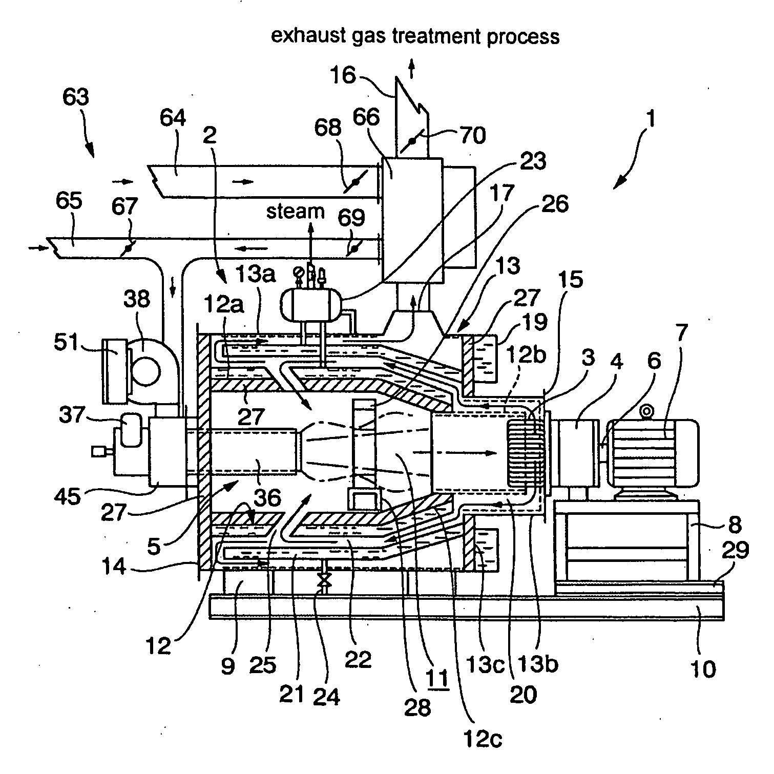
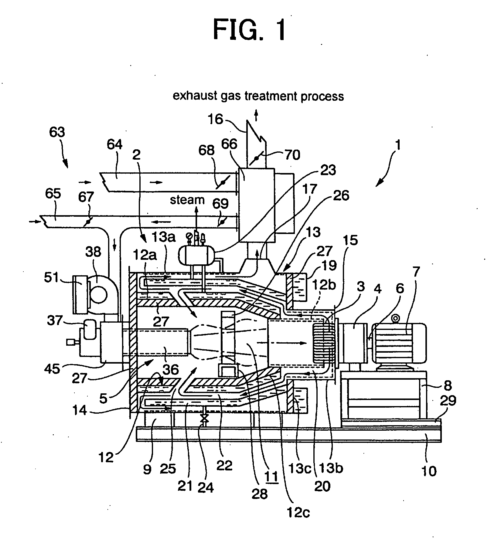
[0052] The following provides a detailed description of the preferred embodiments of the cogeneration system invention with reference to the attached figures. This embodiment of the cogeneration system 1, which is illustrated in FIG. 1, is primarily structured from boiler 2 which uses exhaust gas to heat a liquid medium [i.e., water] and extract thermal energy therefrom, Stirling engine 4 which includes heater 3 and which operates from a sealed operating fluid heated by heater 3, and burner unit 5 that serves as the thermal source from which thermal energy, that is, combustion flames, the thermal radiation from those flames, and combustion-generated exhaust gas, is supplied to boiler 2 and heater 3 of Stirling engine 4. Output shaft 6 of Stirling engine 4 is connected to electrical generator 7 as means of converting thermal energy generated by heater 3 into electricity.

[0053] Stirling engine 4, electrical generator 7, and boiler 2 are mounted in a horizontal orientation to frame 10...


PUM

PropertyMeasurementUnit
temperaturesaaaaaaaaaa
temperatureaaaaaaaaaa
thermal energyaaaaaaaaaa

Abstract

A Stirling engine-equipped cogeneration system is capable of utilizing thermal energy, without waste, and of offering high thermal usage efficiency at every stage of the thermal energy utilization process. The system includes a combustion chamber (11), a burner unit (5) installed to the combustion chamber, the burner unit driving combustion to generates exhaust gas within the combustion chamber, a liquid media jacket (21) that envelopes the combustion chamber, a liquid media flowing within the liquid media jacket and absorbing thermal energy from the burner-generated exhaust gas, a Stirling engine (4) operating from a sealed operating fluid heated by the heater (3) which is located within the combustion chamber facing the burner and subjected to the flow of exhaust gas generated within the combustion chamber, an exhaust gas flow channel (20) through which flows burner-generated exhaust gas after having flowed through and heating the heater, and an exhaust gas passage (22) having an entrance connected to the exhaust gas flow channel as means of allowing the exhaust gas to heat the liquid medium in the liquid media jacket. The exhaust gas generated from the burner-driven combustion flows into the heater to transfer thermal energy thereto, then flows into the exhaust gas passage, through the exhaust gas flow channel to transfer the thermal energy to the liquid medium, thereby heating the liquid medium and heater simultaneously.

Description

TECHNICAL FIELD [0001] The invention relates to a Stirling engine-equipped cogeneration system that does not waste thermal energy, and that offers superior energy utilization characteristics. BACKGROUND ART [0002] The invention relates to Stirling engine-equipped cogeneration system of the type, for example, disclosed in Related Art References (Tokkyo bunken) 1 and 2. [0003] Related Art Reference 1 discloses a cogeneration system assembled from a hydrogen storing heat pump and a Stirling engine equipped with an electrical generator wherein the heater part of the Stirling engine includes a heat-generating fuel-combusting burner located at the center of the upper surface of the combustion case, and further includes combustion air passages being located at the upper wall of the combustion case and leading from an external region to the flame orifice of the burner. In this cogeneration system, the thermal energy lost from the burner is 15% of the total (100%) input thermal energy. [0004...

Claims


Application Information

Patent Timeline
Patent Type & Authority Applications(United States)
IPC IPC(8): F01K25/08C10L1/32F02G5/04F02G1/04F02G1/055
CPCF02G1/055F02G2254/10F02G2254/15Y02E20/14Y02E50/11Y02E20/30Y02E50/10
Inventor SUKIOKA, TETUO
Owner SUGIOKA TETUO
Why Eureka
Try Eureka