Cooling device of engine

Active Publication Date: 2006-09-28
MAZDA MOTOR CORP
View PDF1 Cites 41 Cited by
  • Summary
  • Abstract
  • Description
  • Claims
  • Application Information

AI Technical Summary

Benefits of technology

[0010] The present invention has been devised in view of the above-described things, and an object of the present invention is to provide a cooling device of an engine that can improve an engine's warming-up and achieve a proper emission function

Problems solved by technology

Meanwhile, since the heat exchange between the air supplied to the vehicle cabin and the cooling water is conducted at the heater unit, some heat value is taken from the cooling water at the heater unit, so that there is a limit to the quick warming-up of the engine.
In this case, if the cooling water is supplied to the heater circulation passage, the heating would be conducted at the engine start, but the engine warming-up would be delayed and therefore the properly-heated air would not be supplied to the cabin promptly.
Herein, in the case where the air temperature outside is relatively high, such as in summer, passing the cooling water in the heater circulation passage would bring a prolonged period of the engine warming-up, thereby deteriorating the emission function of the engin

Method used


Image

  • Cooling device of engine
  • Cooling device of engine
  • Cooling device of engine

Examples


Embodiment Construction

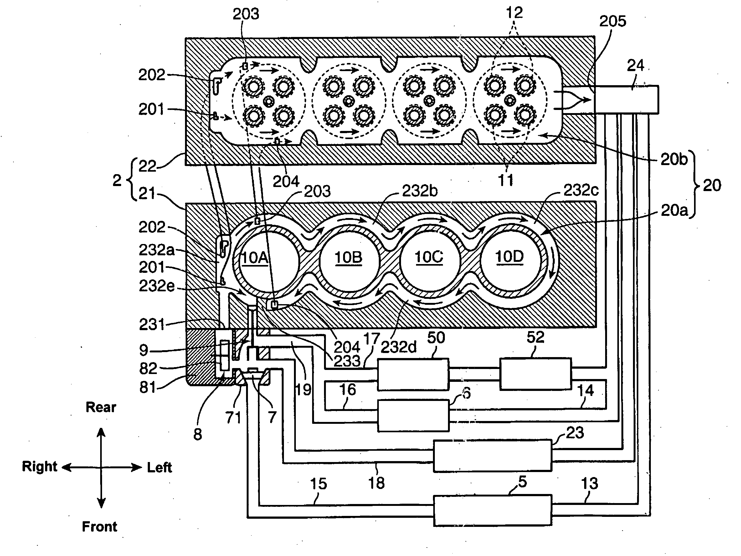
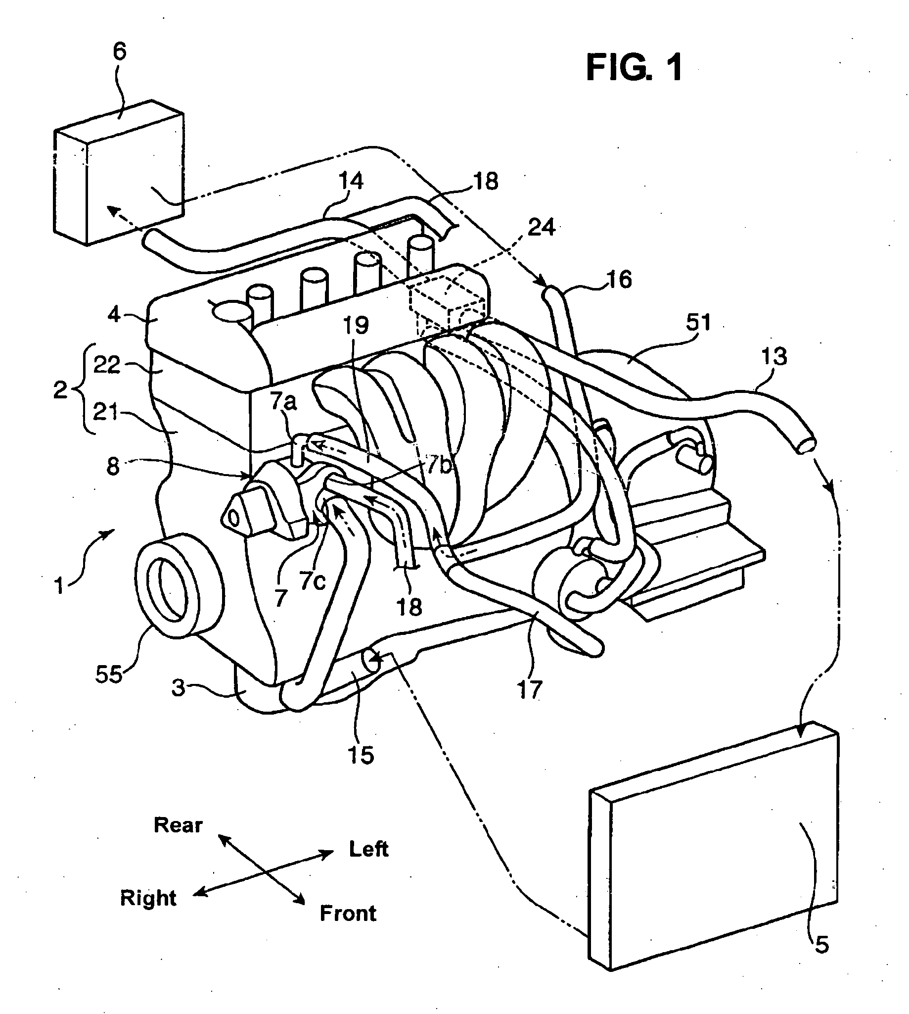
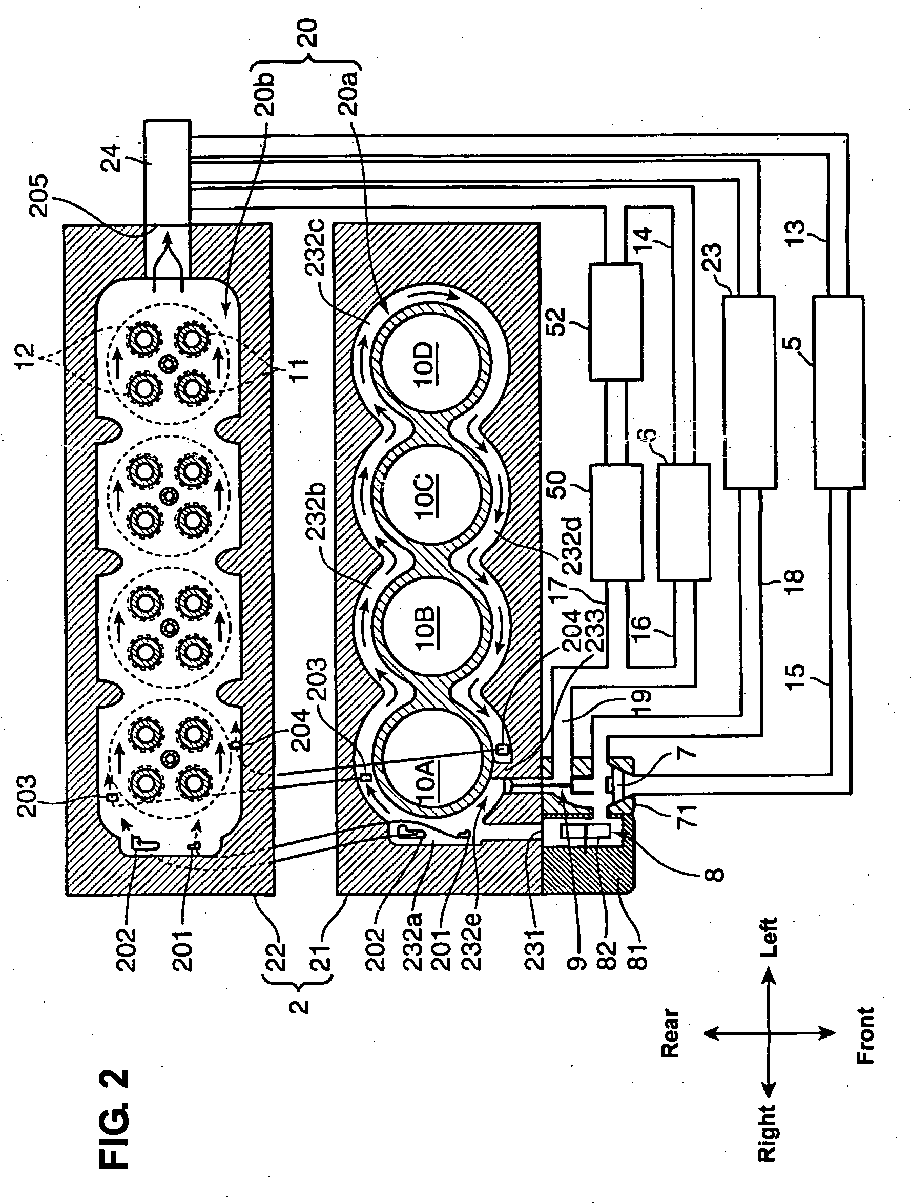
[0046] Hereinafter, preferred embodiments of the present invention will be described referring to the accompanying drawings. FIG. 1 is a schematic perspective view of a cooling device of an engine according to the present invention, and FIG. 2 is an explanatory diagram showing schematically this cooling device.

[0047] An engine 1 is disposed laterally in an engine room behind a engine hood at the front of a vehicle in such a manner that its crank shat extends in a vehicle width direction. The engine 1 is a 4-cylinder inline engine having four cylinders disposed in line, and a cross-flow type of engine, in which intake ports 11 opening at respective combustion chambers of cylinders 10A-10D are disposed at one side of the cylinders and exhaust ports 12 opening at respective combustion chambers of the cylinders 10A-10D are disposed at the other side of the cylinders. Thereby, as shown in FIG. 2, the intake ports 11 are located at the front side of the engine 1, while the exhaust ports ...


PUM


Abstract

There are provided a radiator passage, a thermostat to open and close the radiator passage according to an engine temperature, a heater passage, a flow adjusting device to adjust a flow amount of the coolant that flows in the water jacket according to the engine temperature at an engine start. The flow adjusting device is configured so as to adjust the flow amount of the coolant flowing in the water jacket to be a normal amount when the engine temperature is in an extremely-cold condition, to be zero or smaller than the normal amount when the engine is in a mild-cold condition, and to be the normal amount when the engine is in a warm condition. The heater passage is in opened sate at least when the engine is in the extremely-cold condition.

Description

BACKGROUND OF THE INVENTION [0001] The present invention relates to a cooling device of an engine, in which the engine is cooled with a cooling water that is circulated in a water jacket of the engine and a radiator, a heater unit for heating a vehicle cabin and the like. [0002] A cooling system with the cooling water that is circulated between the water jacket in a cylinder block and a cylinder head and the radiator is known as an engine cooling method. In this system, the heater unit for heating the vehicle cabin with the heated cooling water is generally disposed in a cooling-water circulation passage in parallel to the radiator. [0003] For example, Japanese Patent Laid-Open Publication No. 2004-353632 discloses the cooling device of an engine that comprises the cooling-water circulation passage in which the cooling water is circulated between the water jacket of the engine and the radiator, the heater circulation passage that has a common passage to the cooling-water circulation...

Claims


Application Information

Patent Timeline
IPC IPC(8): F01P7/02B60H1/00
CPCB60H1/00885B60H1/02F01P7/16F01P2003/028F01P2023/00F01P2037/02F01P2060/04F01P2060/045F01P2060/08F01P2070/02
Inventor AOKI, AKINOBUHITOMI, MITSUO
Owner MAZDA MOTOR CORP
Why Eureka
Try Eureka