Laser nozzle cleaning tool

a technology of cleaning tool and nozzle, which is applied in the direction of cleaning process and apparatus, chemistry apparatus and process, electrical apparatus, etc., can solve the problems of difficult to remove sub-100 nanometer (nm) particles from a surface, waste that is environmentally harmful, and high cost of processes, and achieves hardly effective removal of particles on the order of sub-microns or smaller

Inactive Publication Date: 2006-09-28
SEMATECH
View PDF6 Cites 9 Cited by
  • Summary
  • Abstract
  • Description
  • Claims
  • Application Information

AI Technical Summary

Benefits of technology

[0011] For sub 100 nm particles, physical techniques in addition to chemical techniques may be used to separate particles from a surface. Different laser cleaning techniques, such as using a laser interaction with the particle or a liquid-assisted laser cleaning technique may use sudden evaporation of a liquid (e.g., water) on the surface by laser pulses to remove particles from the surface. Further, the present disclosure provides parameters to control the energy transfer to the particle. For example, for the shock wave generation parameters, the droplets size and concentration (e.g., pressure), substrate surface temperature, chemical composition of the droplets may be controlled.

Problems solved by technology

Removal of sub-100 nanometer (nm) particles from a surface can be a challenging subject for semiconductor fabrication processes.
Generally, the particles accumulate when the substrate is being stored or is in a stand-by state between successive processes and may cause defects, particularly for integrated circuits on a substrate.
However, these processes are both expensive and produce waste that is environmentally harmful.
Additionally, the use of a spin brush or an megasonic cleaner can be effective in removing large particles, but are hardly effective in removing particles on the order of submicrons or smaller.
Additionally, Next Generation Lithography (NGL) used in semiconductor technology includes reflective optics on glass substrates which have a surface roughness of approximately 1.5 Angstrom RMS or less to prevent scattering of the light, which may degrade the lithography process performance.
The conventional wet cleaning techniques that use under etching of particles to remove particles from the surface are no longer applicable as they increase the surface roughness beyond the required value.
In addition, most of the current advanced cleaning tools do not have the ability to remove the total particles with size of 27 nm and larger from the surface of the plates.
This is due lack of a mechanism that be able to convey relatively high energy or momentum in distances of few nanometers from the surface.
Additionally, current tools lack a mechanism to increase the population of reactive species in the vicinity of interface.
However, when the focal point of the laser comes close to the surface, the plasma created can touch the surface and can cause damage to the surface.
The referenced shortcomings are not intended to be exhaustive, but rather are among many that tend to impair the effectiveness of previously known techniques concerning particle removal; however, those mentioned here are sufficient to demonstrate that the methodologies appearing in the art have not been satisfactory and that a significant need exists for the techniques described and claimed in this disclosure.

Method used


Image

  • Laser nozzle cleaning tool
  • Laser nozzle cleaning tool
  • Laser nozzle cleaning tool

Examples


Embodiment Construction

[0029] The invention and the various features and advantageous details are explained more fully with reference to the nonlimiting embodiments that are illustrated in the accompanying drawings and detailed in the following description. Descriptions of well known starting materials, processing techniques, components and equipment are omitted so as not to unnecessarily obscure the invention in detail. It should be understood, however, that the detailed description and the specific examples, while indicating embodiments of the invention, are given by way of illustration only and not by way of limitation. Various substitutions, modifications, additions, and / or rearrangements within the spirit and / or scope of the underlying inventive concept will become apparent to those skilled in the art from this disclosure.

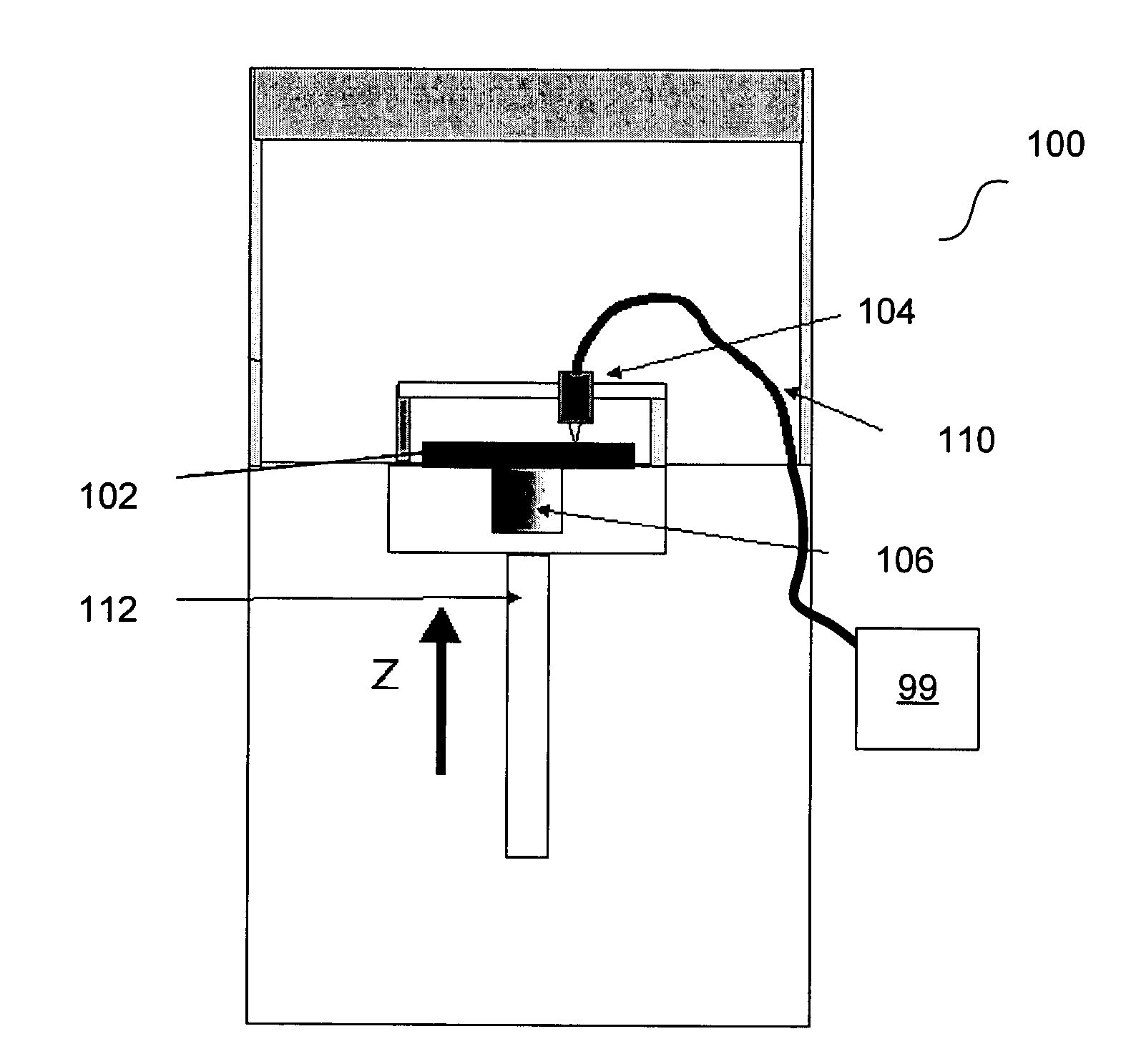
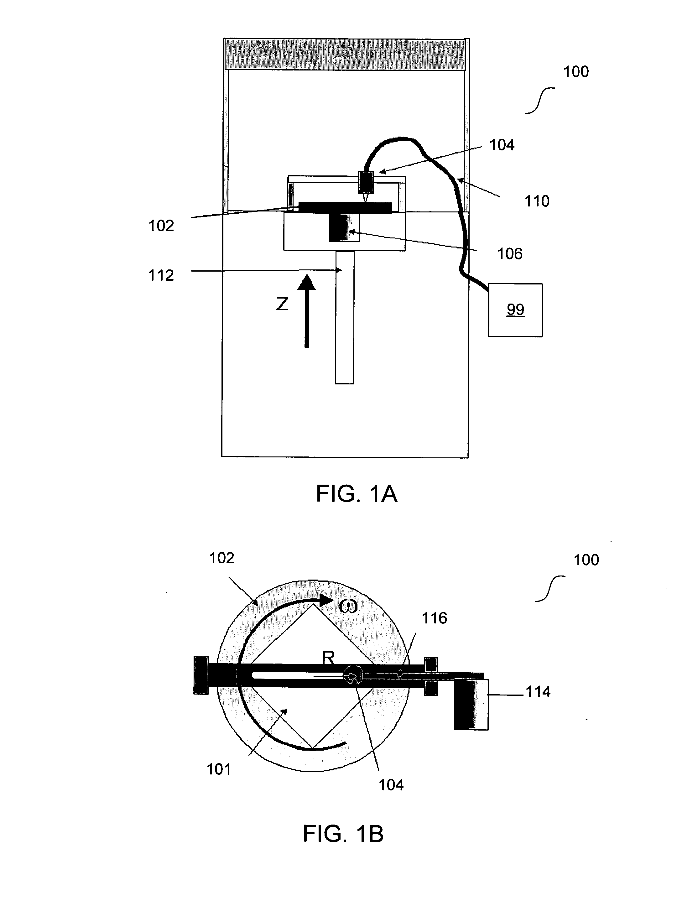
[0030] The present disclosure provides integrating different laser-based cleaning methods with a wet bench approach to control and / or substantially eliminate damage to a surface du...


PUM

PropertyMeasurementUnit
surface roughnessaaaaaaaaaa
sizeaaaaaaaaaa
wavelengthaaaaaaaaaa

Abstract

An apparatus including a laser operating in different cleaning techniques is provided. In one embodiment, the laser interacts with the particle to remove the particle by expansion. In another embodiment, a liquid-assisted laser cleaning technique evaporates a liquid layer on the surface by laser pulses and subsequently removing the particles from the surface. Further, the present disclosure provides parameters to control the energy transfer to the particle. For example, for a shock wave generation parameters, the droplets size and concentration (e.g., pressure), substrate surface temperature, chemical composition of the droplets may be controlled.

Description

[0001] This application claims priority to, and incorporates by reference, U.S. Provisional Patent Application Ser. Nos. 60 / 636,829 and 60 / 636,827, which were filed on Dec. 16, 2004.BACKGROUND OF THE INVENTION [0002] 1. Field of the Invention [0003] The present invention relates generally to semiconductor fabrication processes, and more particularly to an apparatus and method for removing particles from a surface. [0004] 2. Description of Related Art [0005] Removal of sub-100 nanometer (nm) particles from a surface can be a challenging subject for semiconductor fabrication processes. These particles may include contaminants on the surface including materials such as organic material, dust, residue, and metal impurities. Generally, the particles accumulate when the substrate is being stored or is in a stand-by state between successive processes and may cause defects, particularly for integrated circuits on a substrate. [0006] The surface-particle interactions depend on the material a...

Claims


Application Information

Patent Timeline
Patent Type & Authority Applications(United States)
IPC IPC(8): H01L21/306
CPCB08B7/0042H01L21/67028H01L21/67051
Inventor RASTEGAR, ABBAS
Owner SEMATECH
Why Eureka
Try Eureka