Method and joining element for joining workpieces

a technology of joining element and workpiece, which is applied in the direction of threaded fasteners, soldering devices,auxillary welding devices, etc., can solve the problems of limited joint strength and many joining techniques such as self-piercing riveting and clinching, and achieve excellent joining quality and high joining strength

Inactive Publication Date: 2006-09-28
DAIMLER AG +1
View PDF5 Cites 95 Cited by
  • Summary
  • Abstract
  • Description
  • Claims
  • Application Information

AI Technical Summary

Benefits of technology

[0008] It is a primary object of the present invention to provide a method and a joining element for joining at least two adjacent workpieces, with the joint being of high joining strength and excellent joining quality. The joining process is to be performed such th

Problems solved by technology

Many joining techniques such as self-piercing riveting and clinching are not suitable for this purpose.
Apart therefrom that this joining technique requires

Method used


Image

  • Method and joining element for joining workpieces
  • Method and joining element for joining workpieces
  • Method and joining element for joining workpieces

Examples


Embodiment Construction

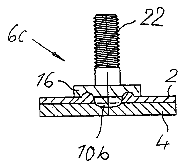
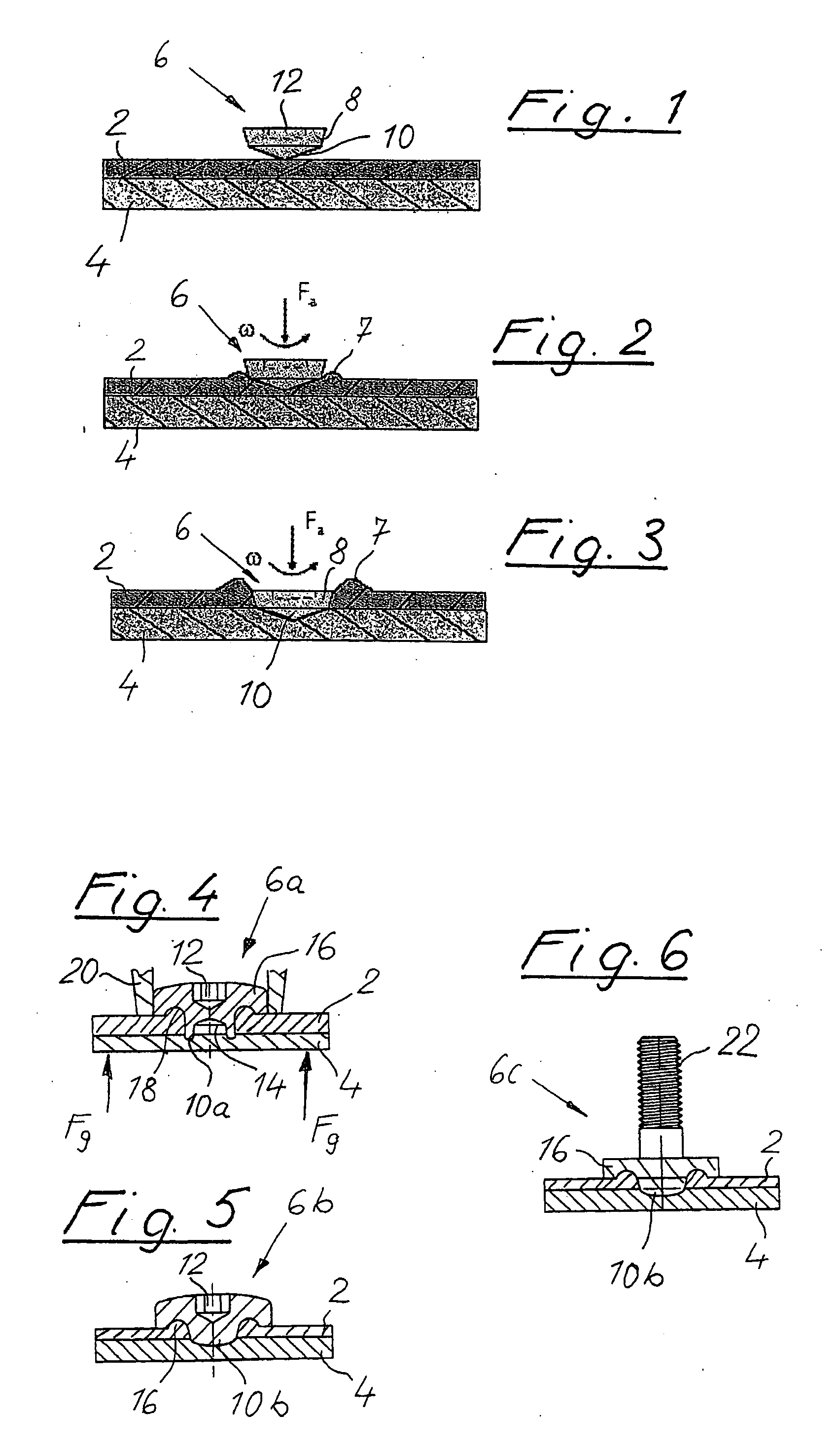
[0025] With reference to FIG. 1, two plate-shaped workpieces 2, 4 in abutment to each other are to be joined by a joining element 6. As an example, the workpiece 2 is a frame member of steel (lower workpiece 4) which is to be “covered” by an aluminium sheet (upper workpiece 2).

[0026] The joining element 6 is, in the embodiment of FIG. 1, a rotationally symmetrical member comprising a conical body portion 8 and a conical penetrating portion 10 terminating in a tip. The body portion 8 is provided with a drive means 12 comprising a recess (e.g. a polygonal depression, a slot, a torx) as indicated by dotted lines.

[0027] For making the joint the joining element 6 is driven by drive means (not shown) so as to perform simultaneous rotational and translational movements as indicated by the arrows Fa and ω, whereby the tip of the conical penetrating portion 10 of the joining element 6 penetrates from above into the material of the workpieces 2, 4.

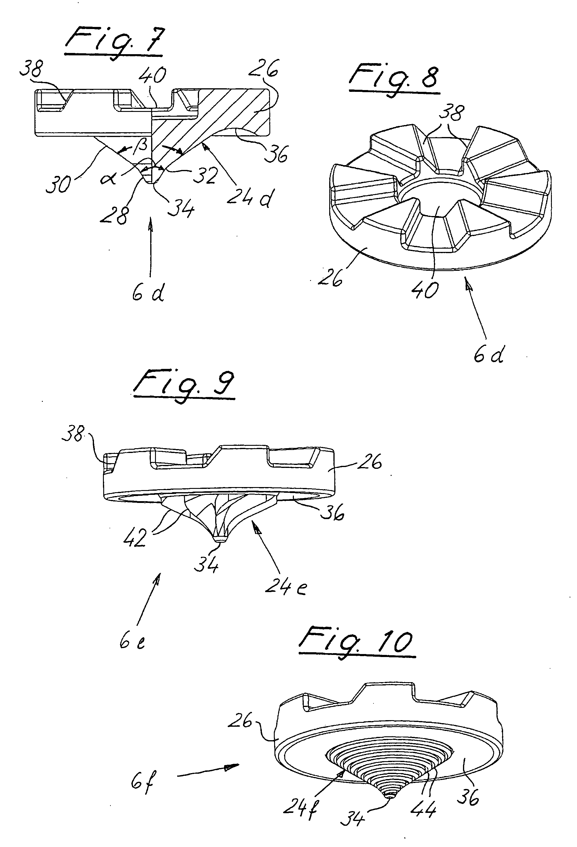
[0028] As shown in FIG. 2 the joining elem...


PUM

PropertyMeasurementUnit
Angleaaaaaaaaaa
Angleaaaaaaaaaa
Angleaaaaaaaaaa

Abstract

A method for joining at least two workpieces in abutment to each other by a joining element. The joining element 6 is driven so as to perform rotational and translational movements in order to be moved through the upper workpiece 2 and into the lower workpiece 4 without full penetration of the lower workpiece in order to provide for an integral one-piece joint between the joining element and the lower workpiece due to friction as a result of said rotational and translational movements. The joining process will result further in a joint between the joining element and the upper workpiece which is mainly a positively interlocking and/or friction joint. The workpieces remain in engagement to each other and are being interconnected. The method enables to join workpieces 2, 4 not only of similar but also of different materials such as aluminium/steel or plastic material/metal. Generally it is sufficient that the joining area is accessible only from one side.

Description

BACKGROUND OF THE INVENTION [0001] The present invention relates to a method for joining at least two workpieces by a joining element. [0002] It is quite often necessary to join workpieces in joining areas where the workpieces are accessible only from one side. Many joining techniques such as self-piercing riveting and clinching are not suitable for this purpose. While there are joining techniques such as joining by blind rivets and screws which allow joining the workpieces from only one side thereof, the joining techniques usually require special measures such as boring holes, deformation of the blind rivet, forming of threads, etc. [0003] DE 196 30 271 C2 discloses a method for joining a workpiece of plastifiable material to another workpiece where a friction element is moved through an upper workpiece into a lower workpiece to generate a plastified process zone and to move such plastified process zone into the area between the two workpieces. Thereafter the friction element is wi...

Claims


Application Information

Patent Timeline
IPC IPC(8): B23K20/12B23K31/02B23K37/00
CPCB21J15/027B23K20/1255B23K20/1265B23K20/127B23K20/2333B23K2203/20B23P19/062F16B5/04F16B37/06B29C65/0672B29C65/069B29C65/562B29C66/1122B29C66/21B29C66/41B29C66/742B29C66/8322B23K2103/20
Inventor RUTHER, MICHAELDICKES, SVENBUONACCORSO, VIRGINIOMESCHUT, GERSONDRAHT, TORSTEN
Owner DAIMLER AG
Why Eureka
Try Eureka