Method for manufacturing heterometallic assembly and heterometallic assembly

a technology of heterometallic assembly and manufacturing method, which is applied in the direction of superstructure connections, arc welding apparatus, metallic material coating processes, etc., can solve the problems of inability to obtain good strength and limited brazing joints, and achieve high joining strength, excellent appearance, and high joining strength

Pending Publication Date: 2022-06-02
KOBE STEEL LTD
View PDF0 Cites 0 Cited by
  • Summary
  • Abstract
  • Description
  • Claims
  • Application Information

AI Technical Summary

Benefits of technology

[0017]According to a method for manufacturing a dissimilar metal joint product of the present invention, it is possible to join different kinds of metals, that is, an aluminum or aluminum-alloy material and a steel material to each other with excellent appearance and high joining strength by an industrially simple method. In addition, according to a dissimilar metal joint product of the present invention, it is possible to obtain high joining strength.

Problems solved by technology

However, joining based on brazing is limited to joining between members of one and the same material due to an industrial technical problem.
When the roof side rail of the steel material is welded directly to the roof panel of the aluminum or aluminum-alloy material by typical arc welding, brittle intermetallic compounds are formed in the joining interface so that good strength cannot be obtained.

Method used


Image

  • Method for manufacturing heterometallic assembly and heterometallic assembly
  • Method for manufacturing heterometallic assembly and heterometallic assembly
  • Method for manufacturing heterometallic assembly and heterometallic assembly

Examples


first embodiment

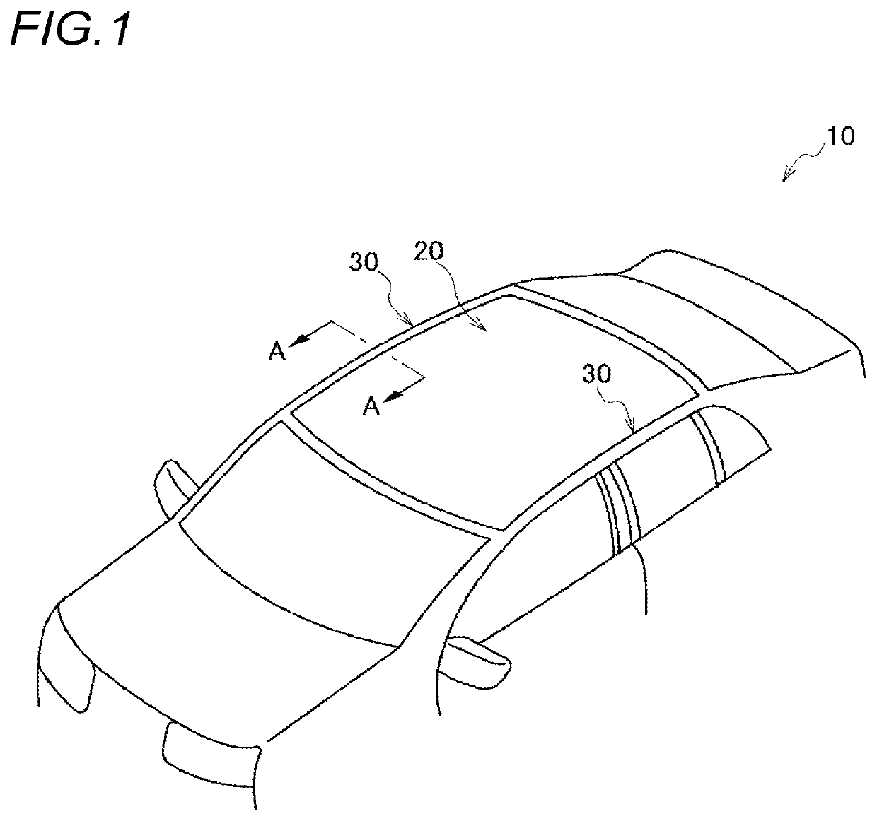
[0025]First, a first embodiment of the present invention will be described. FIG. 1 is a view showing a schematic structure of a vehicle body to which a dissimilar metal joint product is applied. As shown in FIG. 1, a vehicle body 10 of an automobile has a roof panel 20 of an aluminum or aluminum alloy material constituting a roof of the vehicle body 10, and roof side rails 30 of a steel material provided on both sides in the width direction of the vehicle body. The paired roof side rails 30 are provided on the left and right sides of the vehicle body 10 and in the front and rear direction of the vehicle body 10.

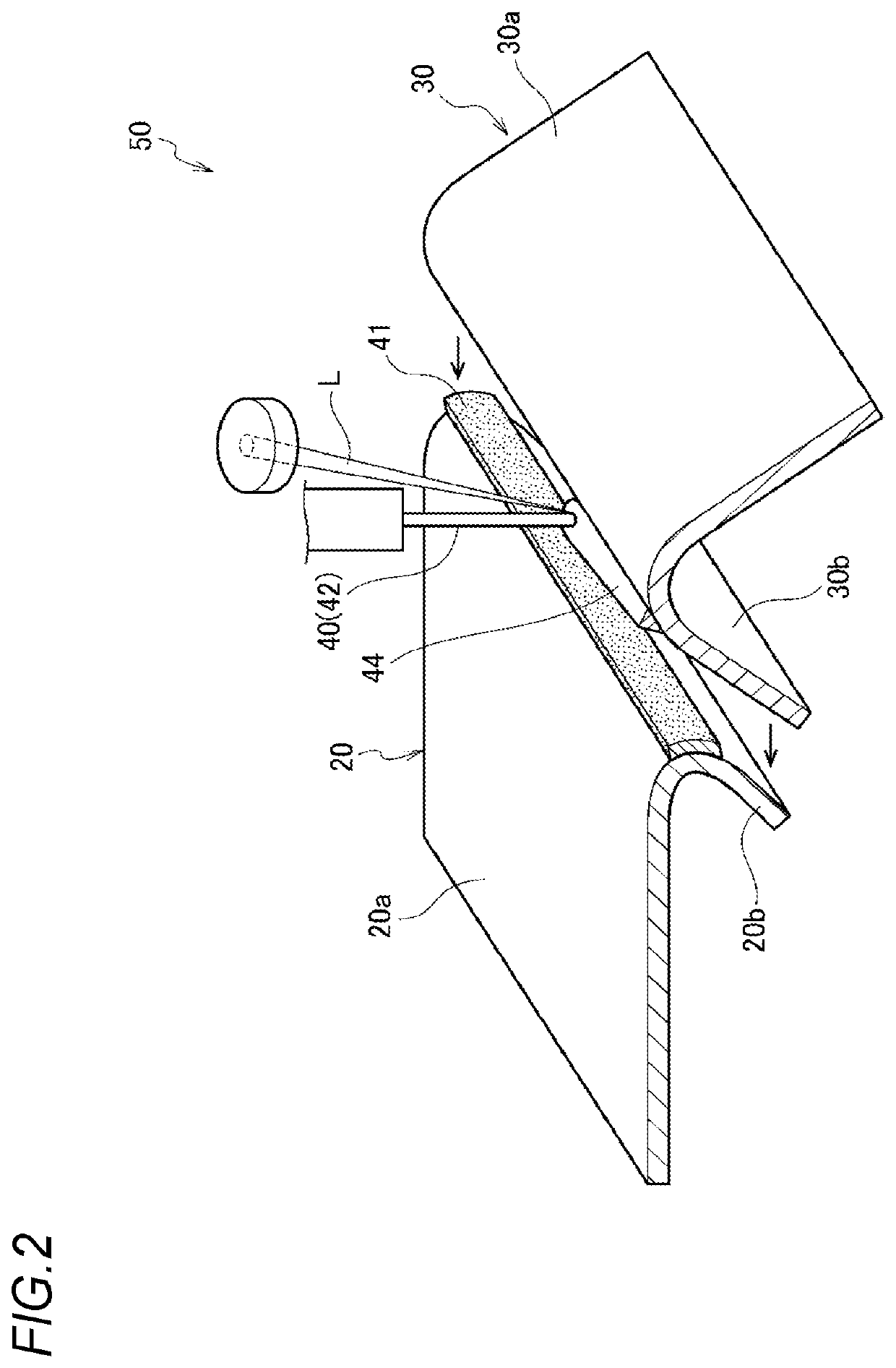
[0026]Next, refer to FIG. 2. The roof panel 20 has a body portion 20a which serves as a roof part of the vehicle body 10, and a bent portion 20b which is bent from an end part of the body portion 20a to the inside of the vehicle body. The bent portion 20b is formed to overlap with an inner flange portion 30b bent from an end part of the body portion 30a in the roof side rails...

second embodiment

[0053]Next, a second embodiment of the present invention will be described. Other than the laser brazing which has been described in the first embodiment, laser welding can be used as the joining method between the steel material 30 and the coating 41. FIG. 4 is a schematic sectional view of a dissimilar metal joint product 50 joined by laser welding using a welding material (welding wire).

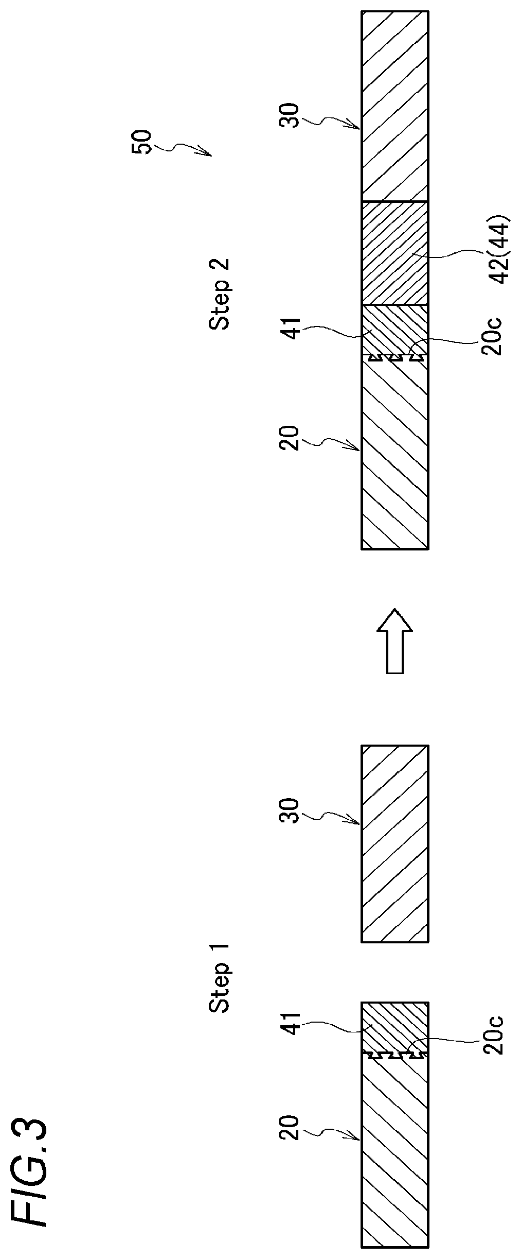
[0054]As shown in FIG. 4, also in the present embodiment, the metal powder is sprayed to at least a part of the surface 20c of the aluminum or aluminum-alloy material 20 at a low temperature and at a high speed to form the coating 41 thereon (Step 1). Next, the aluminum or aluminum-alloy material 20 and the steel material 30 are overlapped such that the coating 41 and the steel material 30 face each other. By laser welding, the coating 41 and the steel material 30 are melted to join the aluminum or aluminum-alloy material 20 and the steel material 20 to each other to thereby manufacture the dissim...


PUM


Abstract

A method for manufacturing a dissimilar metal joint product includes: spraying a metal powder capable of being joined to a steel material to at least a part of a surface of an aluminum or aluminum-alloy material at a low temperature and at a high speed to form a coating thereon; disposing the aluminum or aluminum-alloy material and the steel material such that the coating and the steel material face each other; and performing brazing using a brazing material or welding using a welding material between the coating and the steel material.

Description

TECHNICAL FIELD[0001]The present invention relates to a method for manufacturing a dissimilar metal joint product and a dissimilar metal joint product, and particularly relates to a method for manufacturing a dissimilar metal joint product and a dissimilar metal joint product for main use in a structural member such as a roof, a door or a fender of an automobile.BACKGROUND ART[0002]Two kinds of structures, that is, a mohican structure and a mohican-less structure are used for joining roof members, that is, a roof panel and a roof side rail to each other in a vehicle body of an automobile. The mohican structure has a structurally wide gap (clearance) to which a conventional mechanical joining method can be applied. The mohican-less structure has a narrow gap and an excellent appearance. A spot joining method is generally used for the mohican structure. The mohican structure based on the spot joining method has a sectionally concave joint portion. A step of covering a spot welding mar...

Claims


Application Information

Patent Timeline
Patent Type & Authority Applications(United States)
IPC IPC(8): B23K1/20B23K1/005B62D65/06B62D29/00
CPCB23K1/20B23K1/0056B23K2101/006B62D29/008B62D65/06B23K1/19B23K9/23B23K9/235B23K26/21B62D25/06B62D27/02B23K26/60B23K2103/20B23K2101/18B23K35/302B23K35/3053B23K35/3033C23C24/106B23K35/002B23K35/004B23K35/226B23K1/0008B23K2103/10B23K2103/04
Inventor SUZUKI, REIICHIMAEDA, KYOHEI
Owner KOBE STEEL LTD
Why Eureka
Try Eureka