Welding method

a welding method and welding method technology, applied in welding/soldering/cutting articles, manufacturing tools, transportation and packaging, etc., can solve the problems of limited thickness reduction of side outer panels, hardly achieved reduction of vehicle body weight, and increased size of center pillars, so as to reduce the width dimension of the joining part (such as the flange portion) of each metal plate, the effect of sufficient member strength

Active Publication Date: 2018-12-20
TOYOTA JIDOSHA KK
View PDF0 Cites 2 Cited by
  • Summary
  • Abstract
  • Description
  • Claims
  • Application Information

AI Technical Summary

Benefits of technology

[0016]In general spot welding of an ultra high tensile steel plate, the heat that is generated during the welding causes a heat affected zone around a welding place to be lower in hardness than a base material (part not affected by heat). At this hardness-reduced part, stress concentration is likely to occur when an external force acts, and then no sufficient member strength may be maintainable. According to the aspect, the outside of the heat affected zone around the welding place by the spot welding is heated (heat input is performed thereon) by the laser welding being implemented, and the vicinity of the heat affected zone is tempered as a result. Then, the hardness of the tempered part can become close to the hardness of the heat affected zone. As a result of the above, stress concentration in the heat affected zone is unlikely to occur when an external force acts and member strength improvement can be achieved as a result.
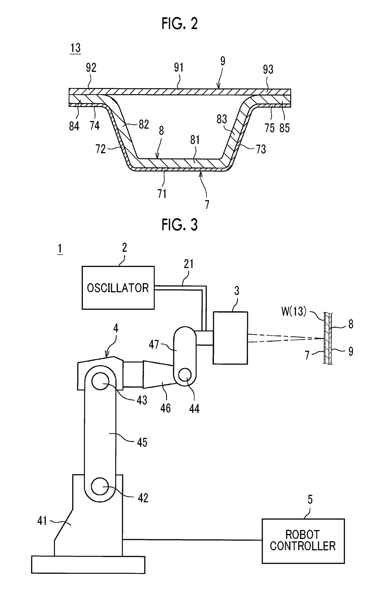
[0017]According to the aspect, the surface plate and the first vehicle body structure plate are joined by the laser light emitted from the surface plate side, and the laser light is scanned on the molten pool including the molten metal of the surface plate and the first vehicle body structure plate melted to stir the molten pool in the places including the place between the welding places of the spot welding after the first vehicle body structure plate and the second vehicle body structure plate are joined by the spot welding when the three or more superposed metal plates including the surface plate, the first vehicle body structure plate, and the second vehicle body structure plate are welded. As a result, the width dimension of the joining part (such as the flange portion) of each metal plate can be reduced, and the thickness of the surface plate can be reduced and each metal plate can be joined with higher joining strength at the same time. As a result, sufficient vehicle body rigidity can be obtained and vehicle body weight reduction can be achieved at the same time.

Problems solved by technology

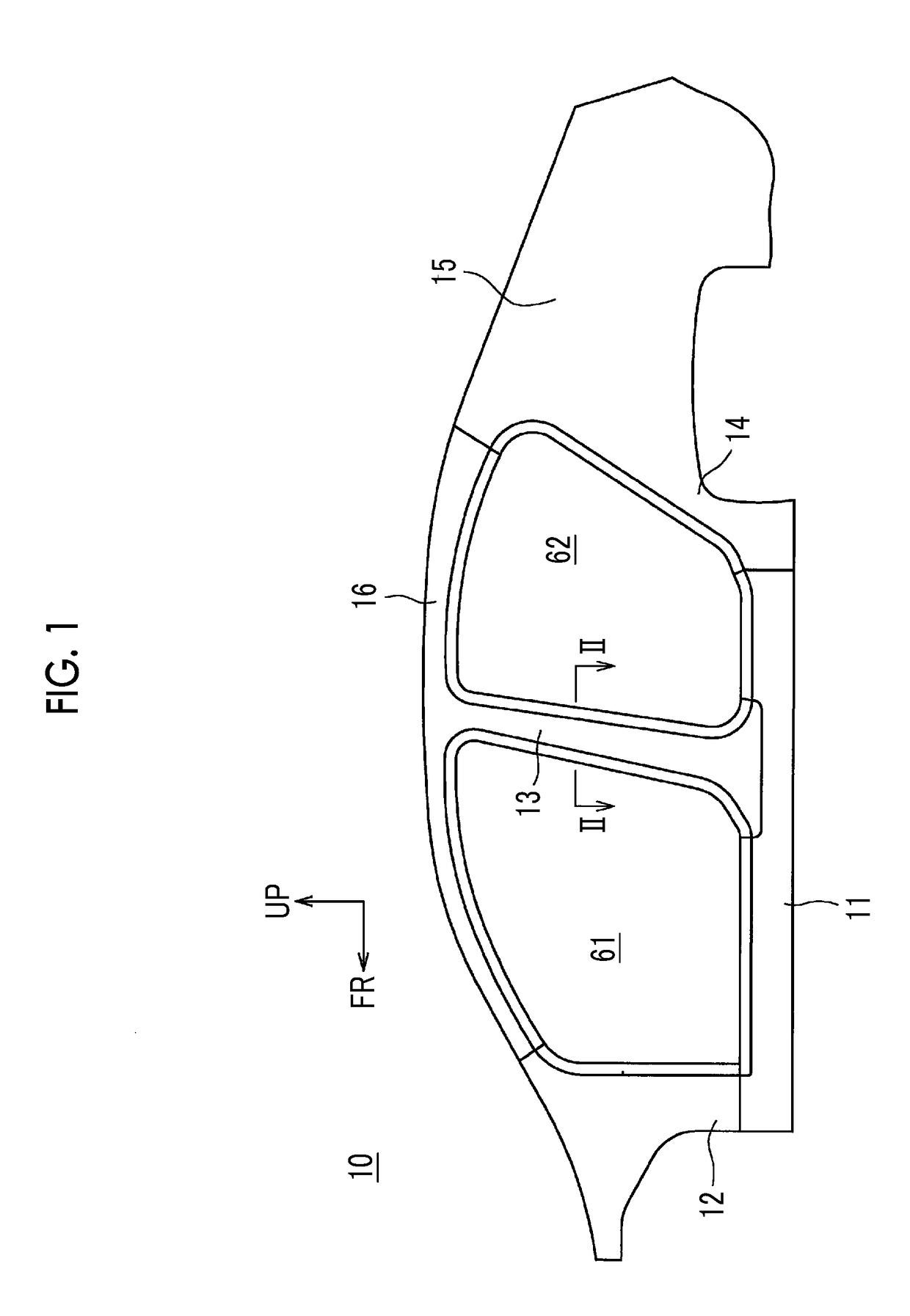
Accordingly, the width dimension of the flange portion of each panel needs to be increased (exceed the diameter of the welding nugget that is needed), and then the size of the center pillar increases and vehicle body weight reduction is hardly achieved.
Although vehicle body weight reduction based on a decrease in the thickness of the side outer panel is desirable in a case where the closed sectional structure that the center pillar inner panel and the center pillar outer reinforcement constitute is responsible for most of vehicle body rigidity, the decrease in the thickness of the side outer panel is limited if the welding nugget is formed also in the side outer panel.
This also hampers vehicle body weight reduction.
Specifically, formation of the welding nugget also in the side outer panel becomes difficult in a case where the ratio of the plate thickness dimension of the side outer panel to the total plate thickness dimension (plate thickness dimension of all of the superposed panels) is less than 1 / 5.
At this hardness-reduced part, stress concentration is likely to occur when an external force acts, and then no sufficient member strength may be maintainable.

Method used


Image

  • Welding method
  • Welding method
  • Welding method

Examples


modification example

[0083]A modification example will be described below. In the present modification example, the center pillar outer reinforcement 8 is a hot stamp material (ultra high tensile steel plate).

[0084]During general spot welding, the heat that is generated during the welding causes a heat affected zone (hereinafter, referred to as a HAZ) lower in hardness than a base material (part not affected by the heat) to be formed around a welding nugget. Softening of the HAZ is particularly noticeable in spot welding with respect to a hot stamp material and an ultra high tension material with a tensile strength equal to or greater than a predetermined value.

[0085]FIG. 10, which corresponds to FIG. 6B, is a diagram illustrating a spot welding step termination time point in a case where the side outer panel 7 is a mild steel plate, the center pillar outer reinforcement 8 is a hot stamp material, and the center pillar inner panel 9 is a high tension material. In FIG. 10, the regions surrounded by the o...


PUM

PropertyMeasurementUnit
thicknessaaaaaaaaaa
thicknessaaaaaaaaaa
thicknessaaaaaaaaaa

Abstract

A welding method for integrally welding three or more superposed metal plates includes a spot welding of joining the first vehicle body structure plate and the second vehicle body structure plate by spot welding in a plurality of places along an opening edge of the door opening portion in a state where each of the metal plates is superposed, and a laser welding of joining the surface plate and the first vehicle body structure plate in a plurality of places including a place between welding places of the spot welding after the spot welding. The joining being performed by emitting laser light to the surface plate and by scanning the laser light to stir a molten pool including a molten metal of the surface plate and the first vehicle body structure plate melted by the laser light.

Description

INCORPORATION BY REFERENCE[0001]The disclosure of Japanese Patent Application No. 2018-100779 filed on May 25, 2018 including the specification, drawings and abstract is incorporated herein by reference in its entirety.BACKGROUND1. Technical Field[0002]The disclosure relates to a welding method for welding three or more superposed metal plates constituting a member around a door opening portion of the vehicle body of an automobile.2. Description of Related Art[0003]In the vehicle body of an automobile according to the related art, a closed sectional structure formed by a plurality of metal plates constitutes a member (such as various pillars) around a door opening portion so that the torsional rigidity of the vehicle body is improved, the deformation amount during a vehicle collision is reduced, and so on. For example, a surface plate as a skin material is welded to the surface of a skeleton member configured to have the closed sectional structure. Accordingly, three or more metal p...

Claims


Application Information

Patent Timeline
Patent Type & Authority Applications(United States)
IPC IPC(8): B23K26/346B23K9/007B23K26/082B23K26/21B23K28/02
CPCB23K2101/006B23K2103/04B23K26/346B23K26/21B23K26/082B23K28/02B23K9/007B23K11/00B23K11/11B23K11/115B23K26/0884B23K26/244
Inventor KAWAKITA, ATSUSHIOGURA, SHUHEISUGINO, HIROKIMIZUNO, WATARUMATSUO, RYUTA
Owner TOYOTA JIDOSHA KK
Why Eureka
Try Eureka