Impeller manufacturing method, impeller, and rotation machine

a manufacturing method and impeller technology, applied in the field of impellers, can solve the problems that the performance of the impeller including such a joining structure tends to be reduced, and achieve the effects of suppressing deformation, reducing material characteristics variation, and ensuring the strength of the joining structur

Active Publication Date: 2021-04-29
MITSUBISHI HEAVY INDUSTIES COMPRESSOR CORP
View PDF0 Cites 0 Cited by
  • Summary
  • Abstract
  • Description
  • Claims
  • Application Information

AI Technical Summary

Benefits of technology

[0019]In the impeller according to the present invention, the first segment and the second segment are joined with the joining layer by the friction welding. As a result, according to the present invention, sufficient joining strength is obtainable even when stainless steel that cannot provide sufficient joining strength in friction stir welding is used for the first segment and the second segment.
[0020]In addition, in the friction welding, there is a part heated to high temperature by frictional heat; however, the part is limited to the joining layer and in the vicinity thereof. Accordingly, a range receiving thermal influence is narrow as compared with brazing in which the members are wholly heated in a furnace. Therefore, the impeller according to the present invention makes it possible to minimize variation of material characteristics caused by joining as well as to suppress deformation caused by application of heat. In other words, according to the present invention, it is possible to provide the impeller high in accuracy of the shape and the dimension.

Problems solved by technology

The impeller including such a joining structure tends to be reduced in performance of the impeller because of low quality of a flow path shape.

Method used


Image

  • Impeller manufacturing method, impeller, and rotation machine
  • Impeller manufacturing method, impeller, and rotation machine
  • Impeller manufacturing method, impeller, and rotation machine

Examples


Embodiment Construction

[0027]A centrifugal compressor 100 that is an example of a rotary machine according to an embodiment of the present invention is described below with reference to accompanying drawings.

[Configuration of Centrifugal Compressor 100]

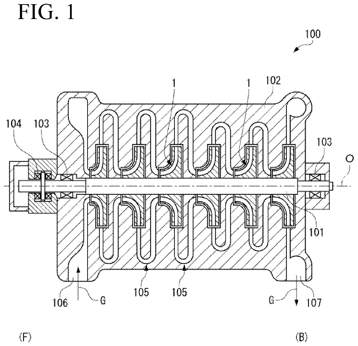
[0028]As illustrated in FIG. 1, the centrifugal compressor 100 according to the present embodiment includes a casing 102 and a rotary shaft 101 that is supported by the casing 102 through a journal bearing 103 and a thrust bearing 104. The rotary shaft 101 is supported so as to be rotatable around an axis line O, and a plurality of impellers 1 that are arranged in the axis line O direction are attached to the rotary shaft 101.

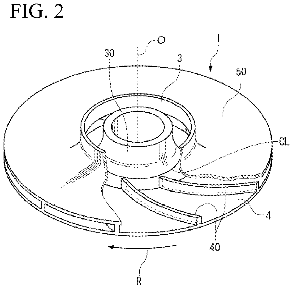
[0029]As illustrated in FIG. 2, each of the impellers 1 includes a substantially disc shape. Each of the impellers 1 is configured to discharge fluid sucked from an induction port 3 that opens on one side of the axis line O direction, from a discharge port 4 on outside in a radial direction through a flow path 105 (see FIG. 1) that is ...


PUM

PropertyMeasurementUnit
temperatureaaaaaaaaaa
rotational forceaaaaaaaaaa
friction pressureaaaaaaaaaa

Abstract

An impeller 1 according to the present invention includes a disc portion 30 fixed to a rotary shaft 101 that rotates around an axis line O, a cover portion 50 disposed to face the disc portion 30, and a plurality of blade portions 40 provided between the disc portion 30 and the cover portion 50. The impeller 1 includes a first segment SG1 configured of a first disc portion 31 that is a portion of the disc portion 30 on one side of the axis line O, a second segment SG2 in which a second disc portion 35 that is a portion of the disc portion 30 on another side of the axis line O, the cover portion 50, and the blade portions 40 are integrally configured, and a joining layer CL configured to join, by friction welding, the first segment SG1 and the second segment SG2.

Description

TECHNICAL FIELD[0001]The present invention relates to an impeller used in a rotary machine.BACKGROUND ART[0002]For example, a rotary machine such as an industrial compressor, a turbo refrigerator, and a small gas turbine includes an impeller in which a plurality of blades are attached to a disc fixed to a rotary shaft. The rotary machine applies pressure energy and speed energy to gas through rotation of the impeller.[0003]As the impeller, a so-called closed impeller in which a cover is integrally attached to the blades has been well-known. The closed impeller includes an impeller assembled by joining a plurality of members. The impeller including such a joining structure tends to be reduced in performance of the impeller because of low quality of a flow path shape. Patent Literature 1 proposes to configure the impeller as a single piece in order to address the issue.[0004]In Patent Literature 1, in the impeller including a disc portion, blade portions, and a cover portion, the disc...

Claims


Application Information

Patent Timeline
Patent Type & Authority Applications(United States)
IPC IPC(8): F04D29/28F04D29/62B23K20/12
CPCF04D29/284B23K2101/001B23K20/12F04D29/624F04D17/122F04D29/023F04D29/266F05D2230/239F04D29/263F04D29/281F04D29/601F05D2230/60
Inventor KONNO, YUYA
Owner MITSUBISHI HEAVY INDUSTIES COMPRESSOR CORP
Why Eureka
Try Eureka