Power line terminating circuit and method, and power line relay device

a technology of terminating circuit and relay device, which is applied in the direction of ignition automatic control, electric controller, instruments, etc., can solve the problems of large terminating circuit size, communication signal deterioration, and environment not always adapted to communication, so as to reduce the influence of noise

Inactive Publication Date: 2006-09-28
TDK CORPARATION
View PDF2 Cites 24 Cited by
  • Summary
  • Abstract
  • Description
  • Claims
  • Application Information

AI Technical Summary

Benefits of technology

[0017] The present invention has been achieved in consideration of the problems and a first object of the invention is to provide a power line terminating circuit and method and a power line relay device which solve the problem of impedance matching irrespective of a device to be connected and which can maintain indoo...

Problems solved by technology

However, the indoor power line is inherently not installed as a communication line, so that the environment is not always adapted to communication.
The technique described in Japanese Patent Laid-open No. 2002-217797 still has, however, a problem which occurs when a general electric device is connected to the terminating circuit 130 for the following reason.
As a result, reflection occurs in the power line terminating circuit, and the communication signal deteriorates.
Also in the case where the capacitor of the line filter is not provided in the input stage of the electric device 5, as shown in FIG. 13, the parasitic line-capacitance of wiring in an electric devi...

Method used


Image

  • Power line terminating circuit and method, and power line relay device
  • Power line terminating circuit and method, and power line relay device
  • Power line terminating circuit and method, and power line relay device

Examples


first embodiment

[0044] First, a power line terminating circuit according to a first embodiment of the invention will be described. Since a power line terminating method according to an embodiment of the invention is embodied by the power line terminating circuit of the embodiment, it will be also described below.

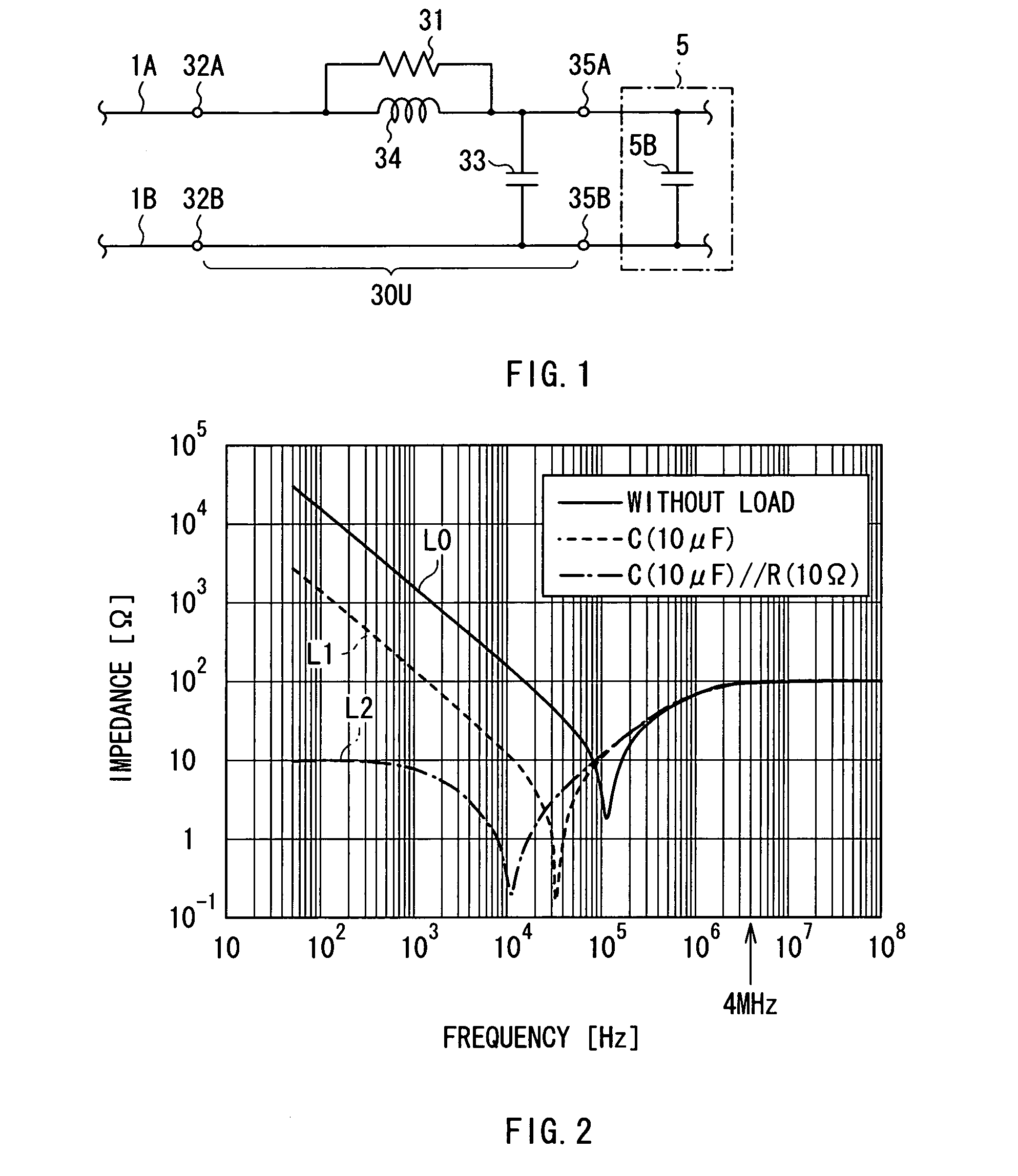
[0045]FIG. 1 shows a circuit configuration of the power line terminating circuit in the embodiment. A power line terminating circuit 30U is applied to, for example, indoor wiring of a general house shown in FIG. 12 and is provided in an outlet (for example, the outlets 2C and 2D in the branch parts B1 and B2 in FIG. 12) provided in an indoor wall. As shown in FIG. 1, the power line terminating circuit 30U is provided between terminations 32A and 32B of a pair of indoor power lines 1A and 1B and a pair of connection terminals 35A and 35B. In this case, the terminations 32A and 32B are wiring ends in wall outlets, and the pair of connection terminals 35A and 35B are socket terminals to which...

first modification

[0073]FIGS. 5A and 5B show a power line relay device according to a first modification of the embodiment as an example where an input and an output are provided in a one-to-one correspondence manner. FIG. 5A shows an outside structure, and FIG. 5B shows a circuit configuration.

[0074] A power line relay device 40 is provided to relay power supply from existing outlets (for example, the outlet 2C in FIG. 12) of the indoor power lines 1A and 1B to the electric device 5. The “existing outlet” is not preliminarily provided on assumption of performing the power line communication but a conventional normal outlet used in a general house.

[0075] As shown in FIGS. 5A and 5B, the power line relay device 40 has a pair of connection plugs 41A and 41B functioning as an input terminal IN, a pair of electric-device-connection sockets 42A and 42B functioning as an output terminal OUT, and a casing 43 housing a power line terminating circuit having the configuration shown in FIG. 5B. The power line...

modification 2

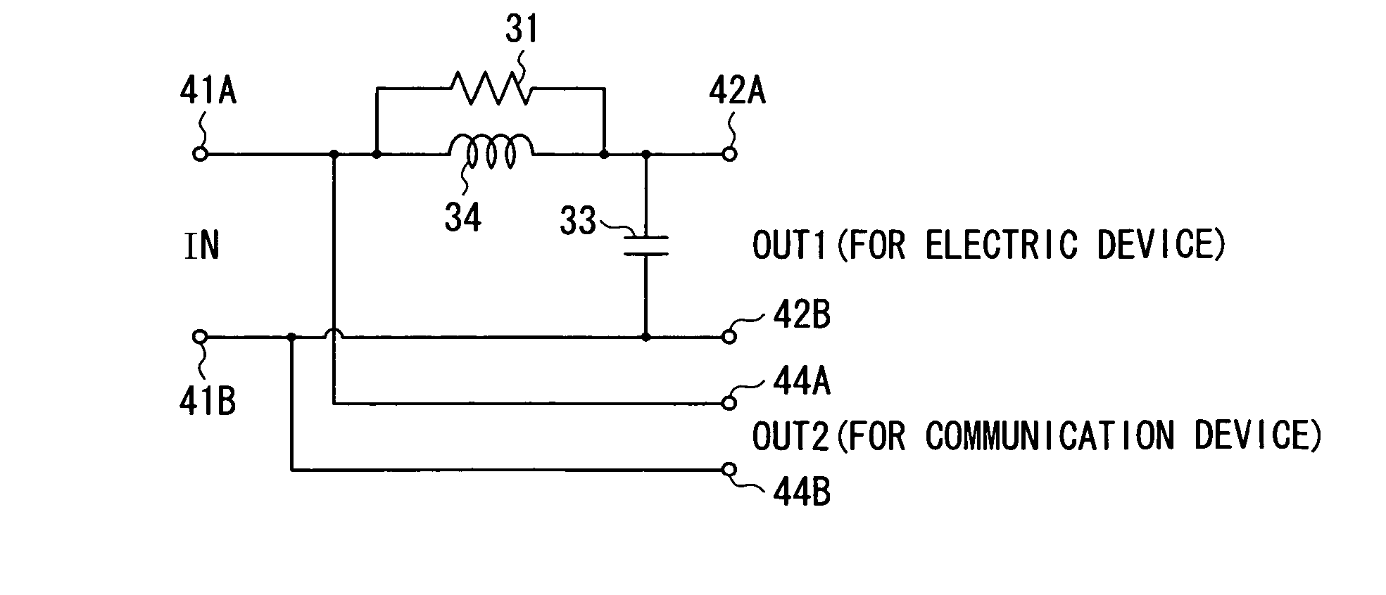
[0079]FIGS. 6A and 6B show a power line relay device according to a second modification of the embodiment as an example where one input and two outputs are provided. FIG. 6A shows an outside structure, and FIG. 6B shows a circuit configuration. The same reference numerals are designated to the same components as those shown in FIGS. 5A and 5B and their description will not be repeated.

[0080] A power line relay device 50 is provided to relay power supply from, for example, the outlet 2A (FIG. 12) as the terminations of the indoor power lines 1A and 1B to the communication device (transmitter 3, receiver 4, or the like) and the electric device 5, and to relay a communication signal among the communication devices and the indoor power lines 1A and 1B.

[0081] The power line relay device 50 has the pair of electric-device-connection sockets 42A and 42B functioning as a first output terminal OUT1 and, in addition, a pair of communication device connection sockets 44A and 44B functioning ...


PUM


Abstract

The present invention provides a power line terminating circuit and method and a power line relay device for setting indoor power lines to a state adapted to communications by making impedances match each other irrespective of a device connected, thereby enabling noise entering from an electric device to the power lines to be reduced. By a capacitor (33) provided between connection ends (35A) and (35B) and an inductor (34) provided between a termination (32A) of an indoor power line (1A) and the connection end (35A), a series resonance circuit having a series resonance point in a frequency band which is higher than a frequency of a power source voltage and is lower than a communication frequency band is configured. A resistor (31) having a resistance value corresponding to a characteristic impedance of the indoor power line (1A) and an indoor power line (1B) is provided in parallel with the inductor (34). Irrespective of the presence or absence and the kind of a load (electric device (5)), an input impedance of a power line terminating circuit (30U) is made constant in the communication frequency band and reflection caused by impedance mismatching at the terminations of the power lines can be prevented. Thus, communication quality of the power line communication can be maintained.

Description

TECHNICAL FIELD[0001] The present invention relates to a power line terminating circuit and method applied to an indoor power line on which an AC power voltage and a high frequency signal of a communication frequency band are superimposed and, to a power line relay device for relaying a terminating end of such an indoor power line and an electric device. BACKGROUND ART [0002] In recent years, to share peripheral devices of a computer, share information of document, still pictures, motion pictures, and the like, games, the Internet, and the like, needs for information communication at home are being grown. Consequently, communication networks are in demand not only in offices but also at home. [0003] Recently, the power line communication technique is regarded as a promising technique as a communication technique used at the time of configuring a communication network in a house, and is being developed. The power line communication technique uses the indoor power line as a signal tra...

Claims


Application Information

Patent Timeline
IPC IPC(8): H02J3/02H03H7/40H03H7/38H04B3/56H04B3/58
CPCH03H7/40H04B3/56H04B2203/5491Y10S307/01H04B3/58H03H7/38H04B3/46
Inventor SUZUKI, MITSUNARI
Owner TDK CORPARATION
Why Eureka
Try Eureka