Organic electroluminescent device

a technology of electroluminescent devices and organic el, which is applied in the direction of discharge tubes/lamp details, discharge tubes luminescnet screens, electric discharge lamps, etc., can solve the problems of difficult to obtain a sufficient lifetime in practice, poor whiteness of conventional organic el devices emitting white lights, and inability to emit white lights. , to achieve the effect of improving light-emitting efficiency, improving whiteness and life of organic el devices

Inactive Publication Date: 2006-09-28
TOYOTA IND CORP
View PDF2 Cites 44 Cited by
  • Summary
  • Abstract
  • Description
  • Claims
  • Application Information

AI Technical Summary

Benefits of technology

[0025] Considering the above mentioned problems, another object of the present invention is to improve whiteness, light-emitting efficiency, and lifetime of organic EL devices having at least an organic light-emitting layer and then a cathode in this order on an anode compared to conventional ones.
[0042] A emission-adjusting layer may be laminated between the red light-emitting layer and the blue light-emitting layer thereby further improving whiteness, light-emitting efficiency, and lifetime. Further, it is preferable for the blue light-emitting layer to be thicker than the red light-emitting layer. “Emission-adjusting layer” here means a layer to adjust the ratio of light-emitting intensities of light-emitting materials.
[0047] According to the present invention, whiteness, light-emitting efficiency, and lifetime of organic EL devices having at least an organic light-emitting layer and then a cathode in this order on an anode can be improved compared to conventional ones not using the present construction.

Problems solved by technology

However, even the above mentioned organic EL devices comprising layers having electron-injecting and electron-transporting functions other than light-emitting layers are difficult to obtain a sufficient lifetime in practice.
Further, there was also a problem that conventional organic EL devices emitting white lights were poor at their whiteness, low in their light-emitting efficiency, and short in their lifetime.

Method used


Image

  • Organic electroluminescent device
  • Organic electroluminescent device
  • Organic electroluminescent device

Examples


first embodiment

The First Embodiment

[0057]>

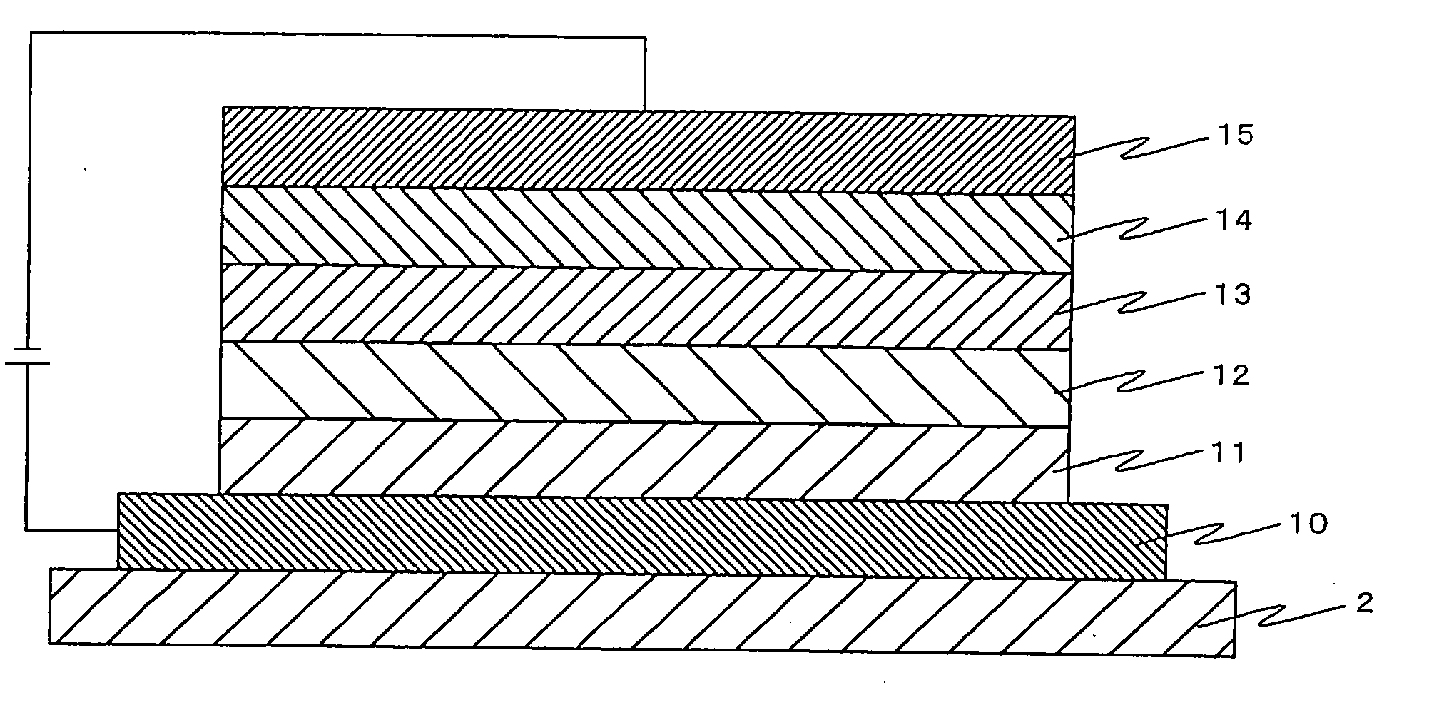
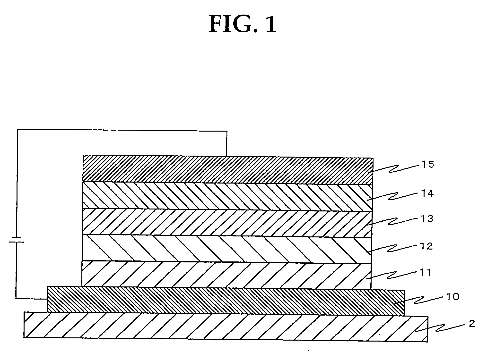
[0058] The present organic EL devices according to the first embodiment have constructions where at least a light-emitting layer, a non-light-emitting layer, an electron-injecting-transporting layer, and then a cathode in this order are formed on an anode. The present organic EL devices according to the first embodiment are characterized in that the non-light-emitting layer of the present invention is laminated between the light-emitting layer and the electron-injecting-transporting layer.

[0059] In the followings, the present organic EL device illustrated in FIG. 1, where anode (10) is formed on substrate (2) and where on anode (10) thus formed, hole-injecting-transporting layer (11), light-emitting layer (12), non-light-emitting layer (13), electron-injecting-transporting layer (14), and then cathode (15) in this order are formed, will mainly be set forth, but naturally, other layer constructions can also be used.

[0060] For example, the light-emitting l...

second embodiment

The Second Embodiment

[0297]>

[0298] In the present organic EL devices according to the second embodiment, at least a red light-emitting layer, a blue light-emitting layer, and then a cathode in this order are formed on an anode, said red light-emitting layer containing a green light-emitting dopant.

[0299]FIG. 5 illustrates the present organic EL device wherein anode (10), hole-injecting layer (31), hole-transporting layer (51), red light-emitting layer (321), blue light-emitting layer (320), electron-transporting layer (54), electron-injecting layer (34), and then cathode (15) in this order are formed on substrate (2). The present organic EL devices according to the second embodiment will now be set forth in more detail with reference to FIG. 5.

[0300]2)>>

[0301] Substrate (2) is usually in a plate form to support the present organic EL devices. In general, organic EL devices consist of very thin layers and thus are prepared on the support of such a substrate.

[0302] Since the presen...

example 1

[0403] Transparent glass substrate (1), on one of whose surfaces anode (10) made of an ITO layer of 250 nm thickness had been formed, was washed with an alkali and then with a pure water, dried, and then cleaned with UV-ozone.

[0404] On anode (2) thus washed and cleaned, using a vacuum vapor deposition apparatus (a carbon crucible, at a vapor deposition speed of 0.1 nm / s, under a vacuum around 5.0×10⁻⁵ Pa), an layer of 50 nm thickness of N,N′-bis(4′-diphenylamino-4-biphenylyl)-N,N′-diphenylbenzidine of the following formula (1) was prepared to be hole-injecting-transporting layer (11).

[0405] On hole-injecting-transporting layer (11), using a vacuum vapor deposition apparatus (a carbon crucible, at a vapor deposition speed of 0.1 nm / s, in vacuo around 5.0×10⁻⁵ Pa), a co-deposited layer of 30 nm thickness of 93.0 weight % of 4,4′-bis(2,2′-diphenylvinyl)biphenyl of the following formula (2) and 7.0 weight % of 4,4′-[bis(9-ethyl-3-carbazovinylene)-1,1′-biphenyl of the following formul...


PUM


Abstract

The present invention provides organic EL devices which have on their anode at least a light-emitting layer, an electron-injecting-transporting layer, and a cathode giving an elongated lifetime, organic EL devices giving a superior whiteness, a higher light-emitting efficiency, and an elongated lifetime compared to conventional ones, and color displays using such organic EL devices. On anode (10), hole-injecting-transporting layer (11), light-emitting layer (12), non-light-emitting layer (13), electron-injecting-transporting layer (14), and cathode (15) in this order are laminated. Otherwise, on an anode, a hole-injecting layer, a hole-transporting layer, a red light-emitting layer, a blue light-emitting layer, an electron-transporting layer, an electron-injecting layer, and a cathode in this order are laminated.

Description

TECHNICAL FIELD [0001] The present invention relates to organic electro-luminescence (EL) devices having on their anode at least a light-emitting layer, an electron-injecting-transporting layer, and a cathode. The present invention relates also to organic EL devices having on their anode at least an organic light-emitting layer and then a cathode in this order. BACKGROUND ART [0002] Conventionally, organic EL devices have been known which have a light-emitting layer(s), containing an organic light-emitting material, between an electrode and a counter electrode, said light-emitting layer(s) generating electro-luminescence (EL) by current between these electrodes. The following functions are required in said light-emitting layer(s). [0003] i) an electron-injecting function [0004] A function for receiving electrons injected from an electrode, that is, a cathode. An electron-injecting property. [0005] ii) a hole-injecting function [0006] A function for receiving holes injected from an e...

Claims


Application Information

Patent Timeline
Patent Type & Authority Applications(United States)
IPC IPC(8): H01J1/62H01L51/50H05B33/14H05B33/22
CPCH01L51/50H05B33/14H01L51/5048H01L51/5036H10K50/00H10K50/125H10K50/14H05B33/22
Inventor NAGARA, YOSHIAKIMURASAKI, TAKANORIMORI, KENJIYAMAMOTO, ICHIROKATO, YOSHIFUMIKAWASAKI, SHINTAROTAKEUCHI, KAZUYOSHI
Owner TOYOTA IND CORP
Why Eureka
Try Eureka