

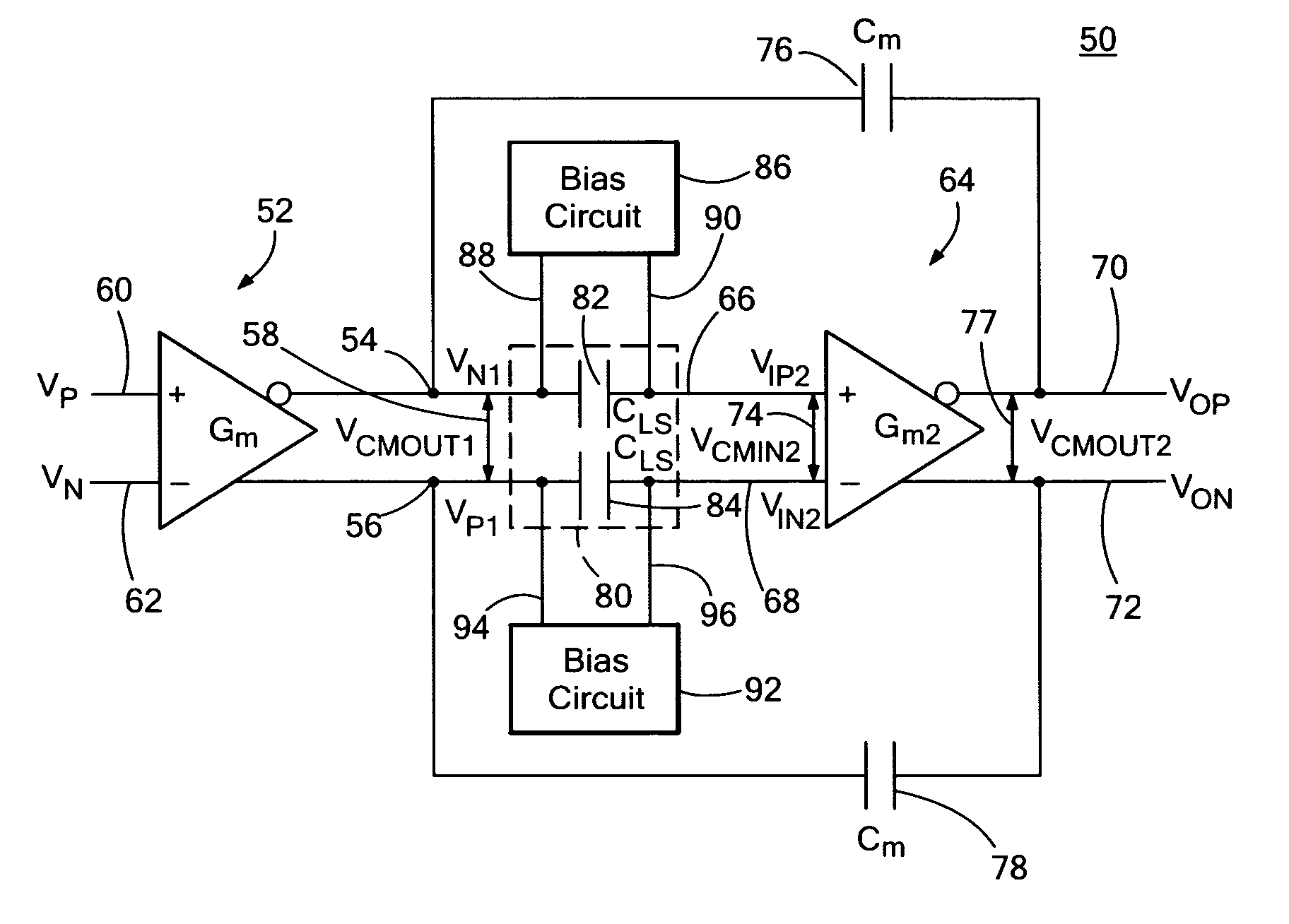
Differential two-stage miller compensated amplifier system with capacitive level shifting
a capacitive level shifting and amplifier technology, applied in the direction of different amplifiers, dc-amplifiers with dc-coupled stages, amplifiers with semiconductor devices/discharge tubes, etc., can solve the problems of limited headroom or signal swing of the second stage, limiting the output common mode voltage of the first stage to one vsub>gs /sub>, and severely restricting headroom and input compliance of the first stage. , to achieve the effect o
- Summary
- Abstract
- Description
- Claims
- Application Information
AI Technical Summary
Benefits of technology
Problems solved by technology
Method used
Image

Examples
Embodiment Construction
[0025] Aside from the preferred embodiment or embodiments disclosed below, this invention is capable of other embodiments and of being practiced or being carried out in various ways. Thus, it is to be understood that the invention is not limited in its application to the details of construction and the arrangements of components set forth in the following description or illustrated in the drawings. If only one embodiment is described herein, the claims hereof are not to be limited to that embodiment. Moreover, the claims hereof are not to be read restrictively unless there is clear and convincing evidence manifesting a certain exclusion, restriction, or disclaimer.
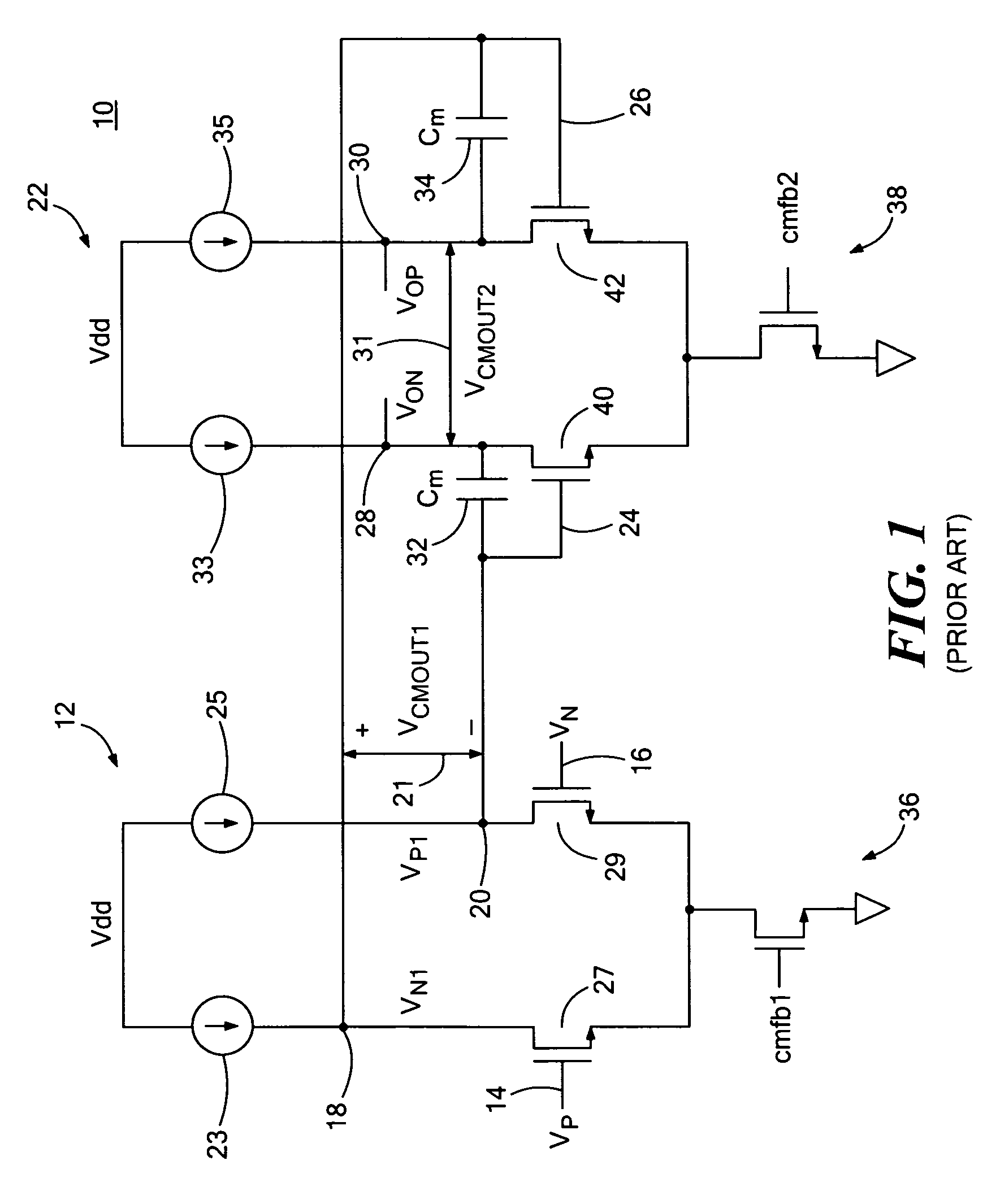
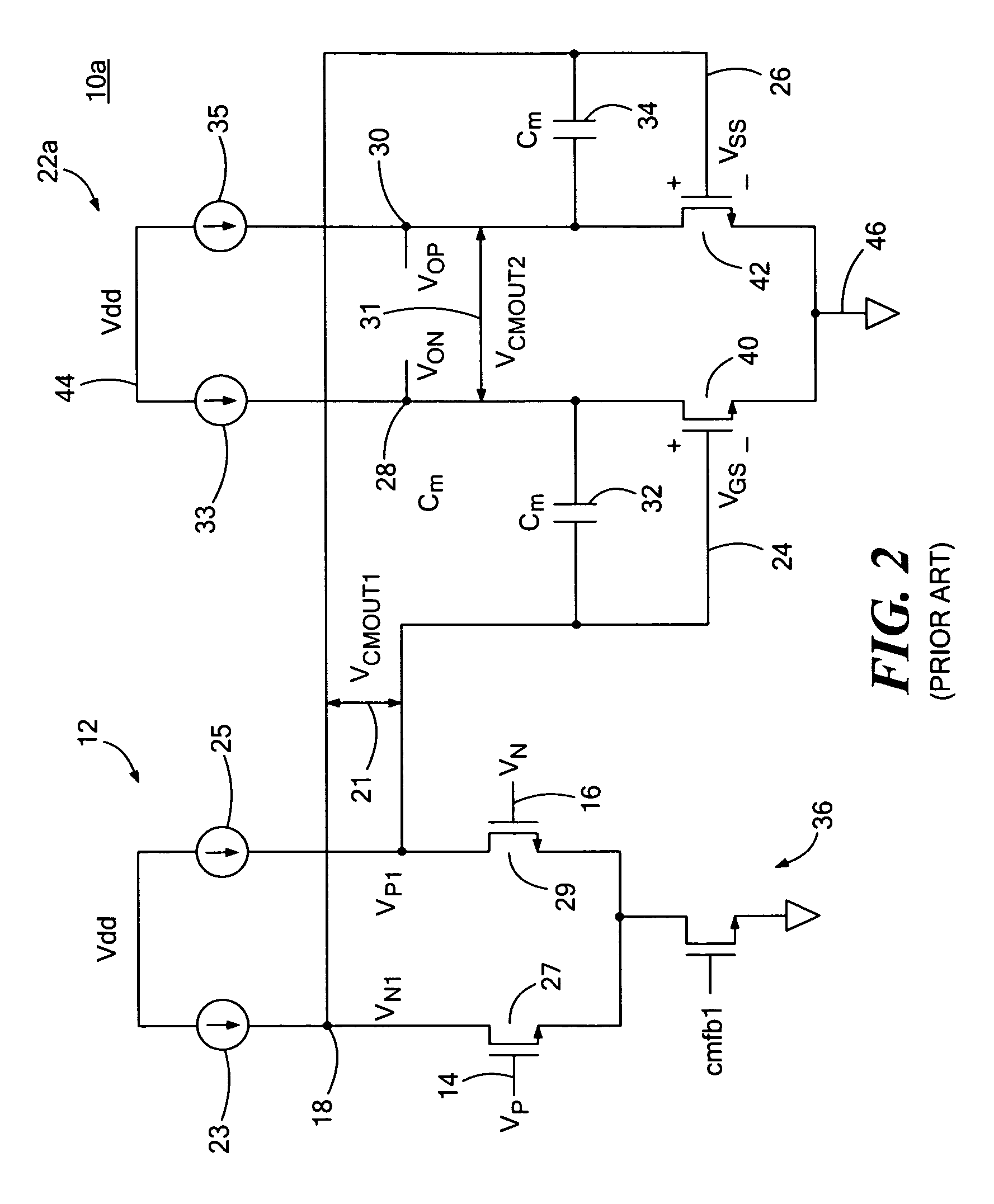
[0026] As discussed in the Background section above, conventional two-stage Miller compensated amplifier system 10 includes first differential transconductance amplifier stage 12 with differential inputs VP 14 and VN 16 and differential outputs VN1 18 and VP1 20. Second differential transconductance amplifier stage 22 inc...
PUM
 Abstract
Description
Claims
Application Information