Antenna, and radio timepiece using the same, keyless entry system, and rf id system

a radio timepiece and keyless entry technology, applied in loop antennas with ferromagnetic cores, instruments, horology, etc., can solve the problems of antenna coil loss, reducing q value and antenna sensitivity, and posing design and ornamental restrictions, so as to achieve low design restrictions, high effective sensitivity, and high sensitivity

Active Publication Date: 2006-09-28
HITACHI METALS LTD
View PDF9 Cites 57 Cited by
  • Summary
  • Abstract
  • Description
  • Claims
  • Application Information

AI Technical Summary

Benefits of technology

[0030] Because the end portions of the magnetic core in the antenna of the present invention are bent in a direction away from a housing, it is less influenced by the housing even when the housing is made of a metal. Accordingly, even when the antenna is disposed in a radio-controlled timepiece having a metal housing, high sensitivity and Q value can be obtained. In a preferred embodiment, branched tip end portions are spread substantially in parallel with a bottom surface of the housing, the magnetic flux coming from any directions can be captured, resulting in higher sensitivity.
[0031] The mounting of a member for forming a magnetic sub-path in addition to the main magnetic circuit provides the following effects: Because a magnetic flux flowing from a magnetic sub-path member also enters a main magnetic path, the amount of a magnetic flux passing through the main magnetic path increases, resulting in higher output voltage. When the case receiving the magnetic main path member constitutes the magnetic sub-path member, a brittle magnetic core can be protected from impact, resulting in high output voltage. The use of a case having such a shape as not to magnetically shut the end portions of the magnetic main path member provides the antenna with little loss.
[0032] The construction of a contact portion of the magnetic sub-path member and the magnetic main path member with a low-permeability material, through which a magnetic flux passes therebetween, reduces a plane-passing magnetic flux by fringing, thereby suppressing the generation of eddy current. The adjustment of inductance (magnetic circuit constants) by changing the cross section area of the low-permeability material and its contact area with the magnetic main path member, which can be done precisely, is much easier and better operable than when the adjustment is done by changing an air gap by the positional adjustment of the magnetic main path member and the magnetic sub-path member.
[0034] Using the antenna of the present invention having the above characteristics, as high sensitivity and Q value as those of radio-controlled timepieces, in which antennas are disposed at positions evading metal housings or metal parts, can be obtained without needing increased installation areas in the radio-controlled timepieces. Accordingly, a radio-controlled timepiece comprising the antenna of the present invention is little restricted in design. In addition, because of little radiation of a magnetic flux by a resonance current, high effective sensitivity is obtained. Such antenna is suitable not only for radio-controlled timepieces, but also for keyless entry systems, RFID systems, etc.

Problems solved by technology

Because as long antennas as more than several hundred meters are needed to efficiently receive these radio waves, it is practically difficult to use them in wristwatches, keyless entry systems, RFID systems, etc.
Thus, there is a metal near the antenna, the energy of a magnetic field is lost as eddy current at the time of resonance, resulting in antenna coil loss and thus decrease in a Q value and antenna sensitivity.
However, the resin case poses restrictions in design and ornament.
However, if the small antenna described in JP 2003-110341 A or JP 8-271659 A is mounted in a wristwatch with a metal case the metal case acts as a radio wave shield, resulting in drastic reduction of receiving sensitivity.
However, because the seal member is indispensable, it suffers restrictions in size reduction and design.
Keyless entry systems and RFID systems also suffer the problem that a metal hinders an antenna from transmitting and receiving radio waves.

Method used


Image

  • Antenna, and radio timepiece using the same, keyless entry system, and rf id system
  • Antenna, and radio timepiece using the same, keyless entry system, and rf id system
  • Antenna, and radio timepiece using the same, keyless entry system, and rf id system

Examples


example 1

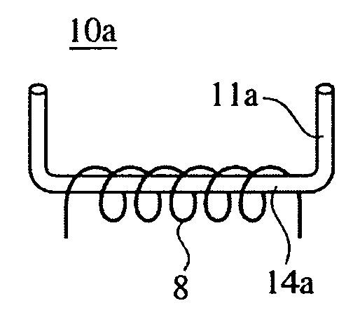
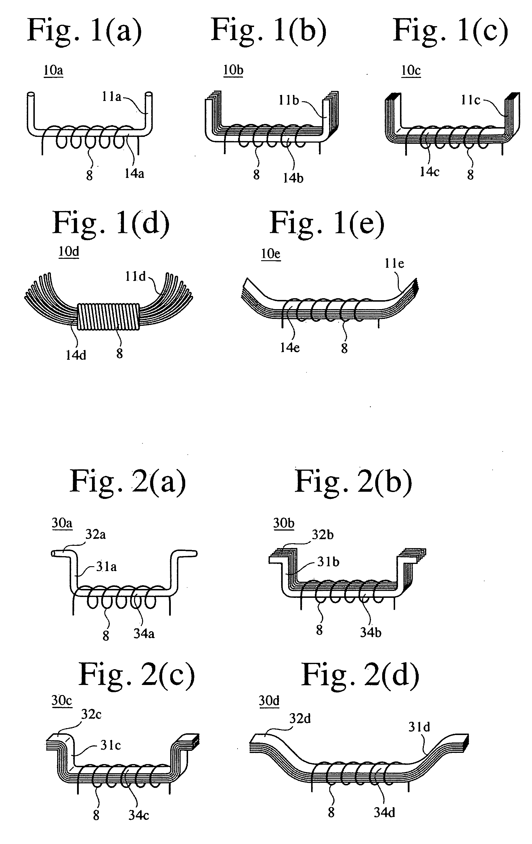
[0131] Using a 1-mm-diameter round ferrite rod available from Hitachi Metals, Ltd. having 7.5-mm-high bent portions at both ends and a 16-mm-long center portion between the bent portions as a magnetic core, it was insulated, and a 0.07-mm-diameter enameled copper wire was wound by 1200 turns around the insulated surface of the ferrite core in a 12-mm-long range, to produce the antenna shown in FIG. 1(a). The installing surface of the antenna was 1 mm wide and 16 mm long.

example 2

[0132] A 15-μm-thick amorphous metal foil was punched in a U shape of 1 mm in width and 16 mm in distance between 7.5-mm-high bent portions, and 30 of these thin foils were laminated to form a 0.45-mm-thick laminate, whose surface was insulated. A 0.07-mm-diameter enameled copper wire was wound by 1200 turns around a center portion of the laminate in a 12-mm-long range, to produce an antenna having the shape shown in FIG. 1(b).

example 3

[0135] An antenna having a magnetic sub-path member was produced to measure output voltage and a Q value. The antenna of Example 2 was provided with a magnetic sub-path member 25d to produce the antenna shown in FIG. 4(d). The magnetic sub-path member 25d was constituted by the same thin ribbons (15-μm-thick amorphous metal foils) as in the magnetic core laminate, and the gap G was 1 mm. To confirm the effect of the magnetic sub-path member 25d, the antenna of Example 2 was measured with respect to output voltage and a Q value.


PUM


Abstract

A magnetic sensor-type antenna comprising a magnetic core and a coil wound around the magnetic core for receiving electromagnetic waves, which is disposed in a housing such that the end portion of the magnetic core is bent away from the housing or a metal portion of the housing, and a timepiece, a keyless entry system and an RFID system each comprising such an antenna.

Description

FIELD OF THE INVENTION [0001] The present invention relates to a magnetic sensor-type, radio wave-receiving antenna suitable for radio-controlled timepieces receiving radio waves including time information for time adjustment, smart keyless entry systems for detecting the access of owners by radio waves to open keys of automobiles or a houses, etc. (hereinafter referred to as “keyless entry systems”), or RFID tag systems for giving and receiving information by modulation signals carried by radio waves (hereinafter referred to as “RFID systems”), etc. BACKGROUND OF THE INVENTION [0002] A radio-controlled timepiece receiving time information conveyed by a carrier wave having a predetermined frequency to adjust its own time based on that time information has been finding various applications such as clocks, wristwatches, etc. [0003] The radio waves used for the radio-controlled timepieces, etc. are 40-200 kHz, having as long wavelengths as several kilometers. Because as long antennas a...

Claims


Application Information

Patent Timeline
Patent Type & Authority Applications(United States)
IPC IPC(8): H01Q7/08G04G21/04G04G99/00G04R60/12H01Q1/27
CPCG04G21/04H01Q1/273H01Q7/08G04R60/12
Inventor ARAKI, HIROKAZUMITA, MASAHIROMITSUMATA, CHIHARU
Owner HITACHI METALS LTD
Why Eureka
Try Eureka