
Method, apparatus, and system for evaluating faulty point in multi-stage optical amplifying and repeating transmission line

Inactive Publication Date: 2006-09-28
FUJITSU LTD
View PDF10 Cites 12 Cited by
  • Summary
  • Abstract
  • Description
  • Claims
  • Application Information

AI Technical Summary

Benefits of technology

[0011] An object of the present invention is to provide a method, apparatus, and system for evaluation of a faulty point in a multi-stage optical amplifying and repeating transmission line which enable as high a speed of fault searches as with the DCR method of course, eliminate the problems in the DCR method, and enable realization of searches for faults even in the vicinity of the midpoint.

Problems solved by technology

Such extremely long distance optical submarine cables have a high probability of breakage and other faults due to various factors.
In addition, searching for a faulty point in that very long distance, in particular searching for it quickly, is becoming increasingly difficult.
However, to provide a high level of quality of service, taking several hours or another long time for searching for a fault is unacceptable.
However, even if performing this search automatically using software, several seconds to several tens of seconds are required for the command response operation for each optical amplifying repeater, so sometimes a tremendous amount of time of several hours ends up being taken.
However, with the DCR method utilizing the power supply system, there are the problems that (i) from the nature of the DCR method, detection of faults occurring near the midpoint of an optical submarine cable is difficult and (ii) with a fault occurring at an optical submarine cable, the DC resistance will fluctuate depending on the state of the fault, for example, the location of breakage of the optical submarine cable, and therefore stable identification of the faulty point will not be possible.
That is, the DCR method enables high speed fault searches, but it is difficult to get high speed fault searches which always give reliable and stable results for faults occurring at an optical submarine cable.

Method used


Image

  • Method, apparatus, and system for evaluating faulty point in multi-stage optical amplifying and repeating transmission line
  • Method, apparatus, and system for evaluating faulty point in multi-stage optical amplifying and repeating transmission line
  • Method, apparatus, and system for evaluating faulty point in multi-stage optical amplifying and repeating transmission line

Examples


Embodiment Construction

[0029] Preferred embodiments of the present invention will be described in detail below while referring to the attached figures.

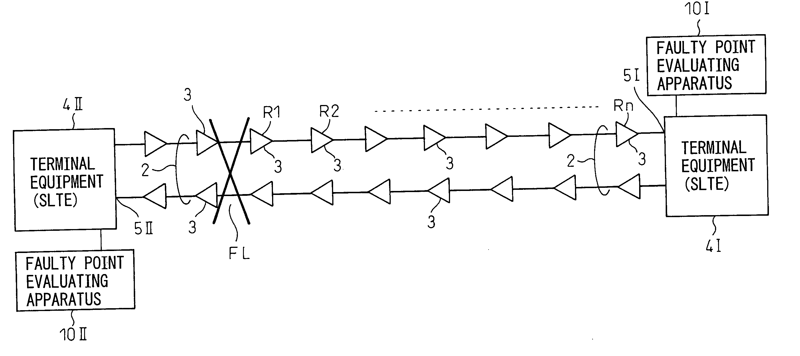
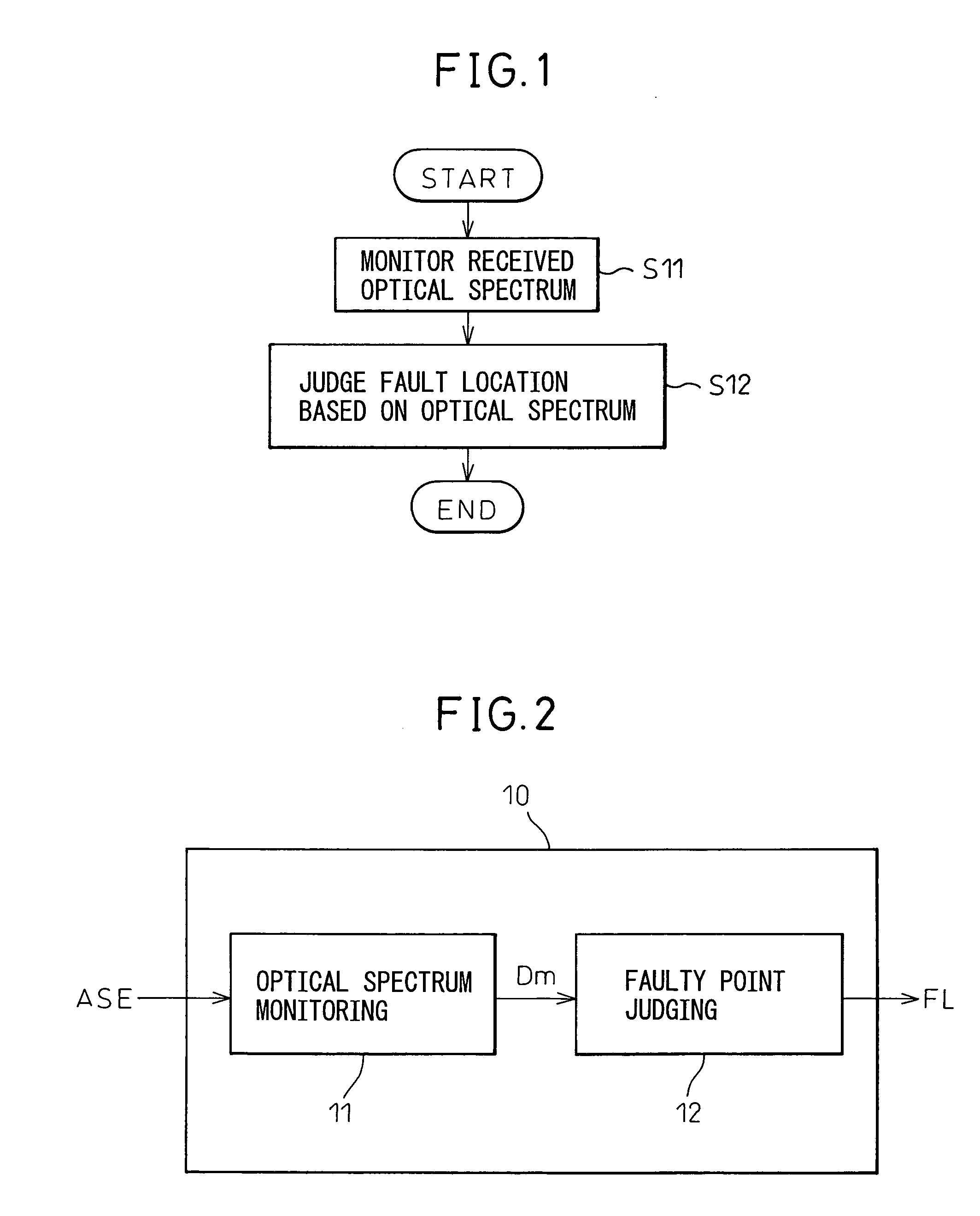
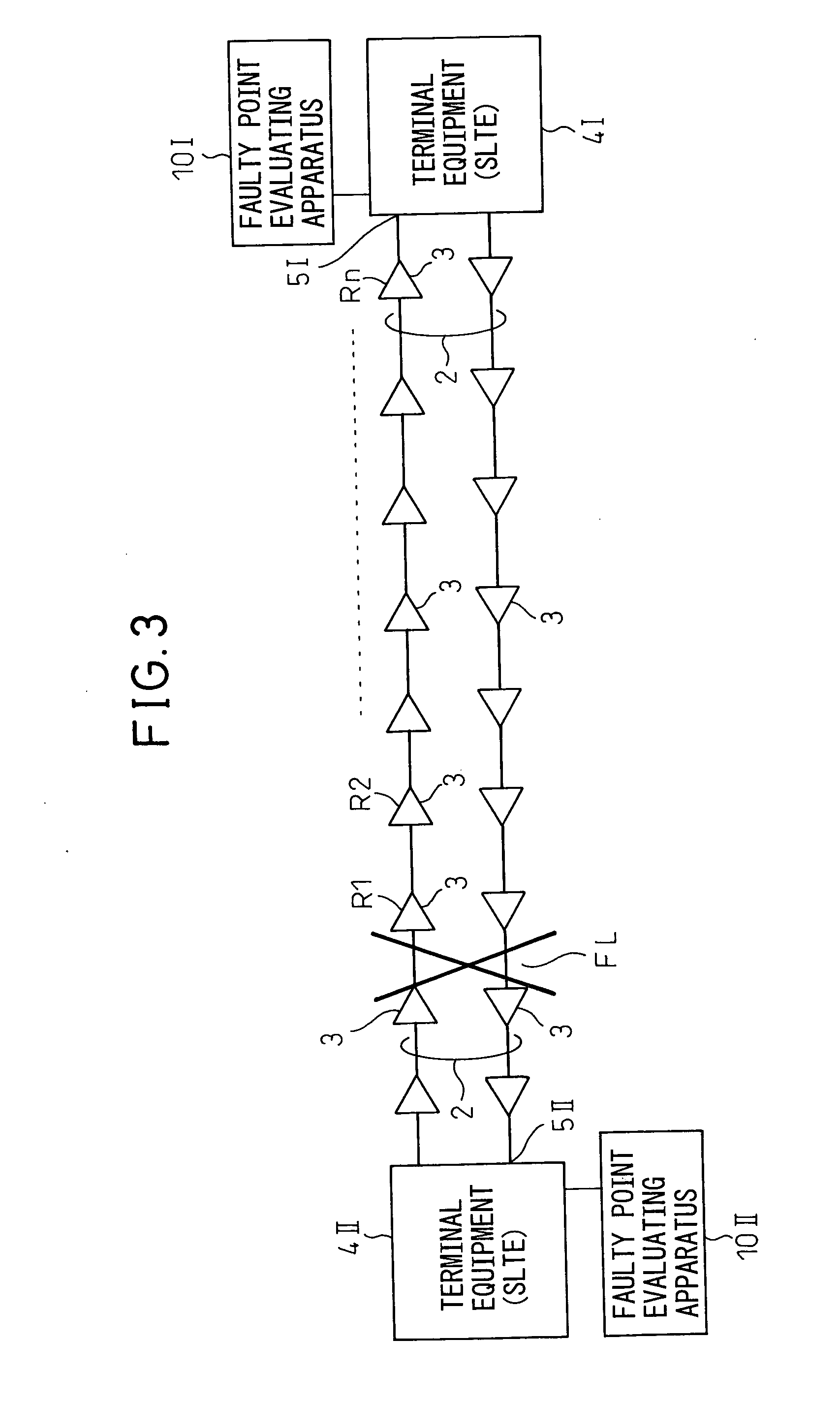
[0030]FIG. 1 is a flow chart showing a method for evaluating a faulty point based on the present invention. The method of evaluation of this figure is predicated on a method of evaluating a faulty point in a multi-stage optical amplifying and repeating transmission line (optical submarine cable system) where a plurality of optical amplifying repeaters are inserted at predetermined intervals in an optical cable and is based on a first step S11 and a second step S12 shown in the figure.

[0031] The first step S11 is a step of monitoring at a light receiving end of the optical cable the optical spectrum of an optical noise signal successively amplified through a chain of optical amplifying repeaters at a downstream side of the faulty point, while the second step S12 is a step of judging the fault location from the monitored optical spectrum of the optical nois...


PUM


Abstract

A method, apparatus, and system for evaluation of a faulty point in a multi-stage optical amplifying and repeating transmission line which provides a totally new technique for searching for faults neither of the typical “command response type” or the “DCR method”. When a fault occurs in an optical submarine cable, the profile exhibited by the optical spectral characteristics of the optical noise signal (ASE) successively amplified through the chain of optical amplifying repeaters at the downstream side of the faulty point changes in accordance with the number of the repeaters. The technique finds the number of the repeaters until the faulty point based on the change in the profile so as to evaluate the location of the faulty point and has a step (S11) of monitoring the optical spectrum at the light receiving end and a step (S12) of determining the location of the faulty point from the monitored optical spectrum.

Description

BACKGROUND OF THE INVENTION [0001] 1. Field of the Invention [0002] The present invention relates to a method for evaluating a faulty point occurring in the middle of a multi-stage optical amplifying and repeating transmission line, particularly a transmission line of an optical submarine cable engaged in multi-stage optical amplifying and repeating operations, an apparatus for evaluating a faulty point, and a system for evaluating a faulty point. Note that below, an optical submarine cable using an optical fiber as a signal transmission line will be explained as a preferable example. [0003] 2. Description of the Related Art [0004] As is well known, optical submarine cables are used for extremely long distance optical transmission of as much as several 1000 km for example for crossing the oceans. Such extremely long distance optical submarine cables have a high probability of breakage and other faults due to various factors. In addition, searching for a faulty point in that very lon...

Claims


Application Information

Patent Timeline
IPC IPC(8): H04B10/00H04B10/079H04B10/07H04B10/29H04B10/291H04B17/40
CPCH04B10/0791H04B10/07953H04B10/0797
Inventor YOKOTA, IZUMIYAMAGUCHI, KATSUJI
Owner FUJITSU LTD
Features
  • Generate Ideas
  • Intellectual Property
  • Life Sciences
  • Materials
  • Tech Scout
  • Unparalleled Data Quality
  • Higher Quality Content
  • 60% Fewer Hallucinations
Learn More