Optically-induced treatment of internal tissue

a technology of internal tissue and optical induction, which is applied in the field of treatment and/or diagnostics of internal tissue, can solve the problems of waste heat dissipation, difficult access to internal tissue, and limited optical channels to target tissue, and achieve the effect of fast treatment times and high speed

Inactive Publication Date: 2006-09-28
RELIANT TECH INC
View PDF36 Cites 36 Cited by
  • Summary
  • Abstract
  • Description
  • Claims
  • Application Information

AI Technical Summary

Benefits of technology

[0012] One advantage of using counter-rotating disks is that the facets can be individually designed. Hence, irregular and non-planar irradiation patterns can be implemented. Another advantage is that the disks can be rotated at high speeds, resulting in fast treatment times.

Problems solved by technology

One difference between the treatment of internal tissue and the treatment of external tissue (e.g., skin) is that internal tissue is more difficult to access.
As a result, the optical channel to the target tissue typically is much more confined since it is limited by the anatomy of the body.
In addition, the channel may also have thermal or other restrictions that limit the amount of waste heat that can be dissipated or the amount of physical debris that can be removed, for example.
It may also be difficult to control the position or movement of the treatment device, to determine the position of the device relative to the target tissue or to obtain feedback about the efficacy of the treatment.
However, this approach has many drawbacks.
For example, high power laser beams are inherently more dangerous and can cause more damage if delivered to the wrong location.
Traditional systems also are typically based on more expensive types of lasers and do not take advantage of lower power, cheaper semiconductor lasers.
The delivery optics must also be designed to handle higher powers, further increasing the cost and complexity of the system.
In addition, if the single laser beam must be manually moved to different locations on the target tissue, this can result in long treatment times.

Method used


Image

  • Optically-induced treatment of internal tissue
  • Optically-induced treatment of internal tissue
  • Optically-induced treatment of internal tissue

Examples


Embodiment Construction

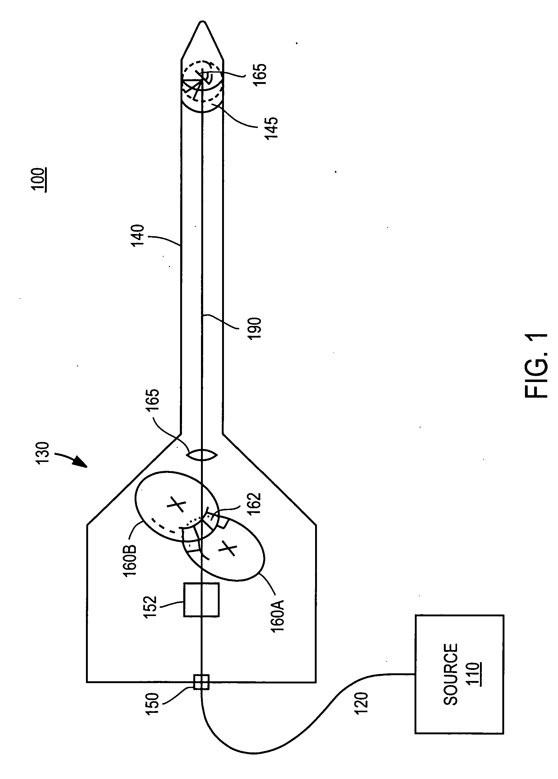
[0030]FIG. 1 is a perspective view of a system 100 according to the present invention. The system 100 includes an optical source 110, an optical fiber 120 and a handpiece 130. The handpiece 130 includes a probe portion 140 used for insertion into the human body. The optical train within the handpiece 130 includes an input port 150 for the fiber, collimating optics 152, two counter-rotating disks 160A-B, and additional delivery optics 165. The probe 140 includes a transparent window 145 located in the vicinity of the probe's tip. In this example, the window 145 is located on the cylindrical side of the probe 140.

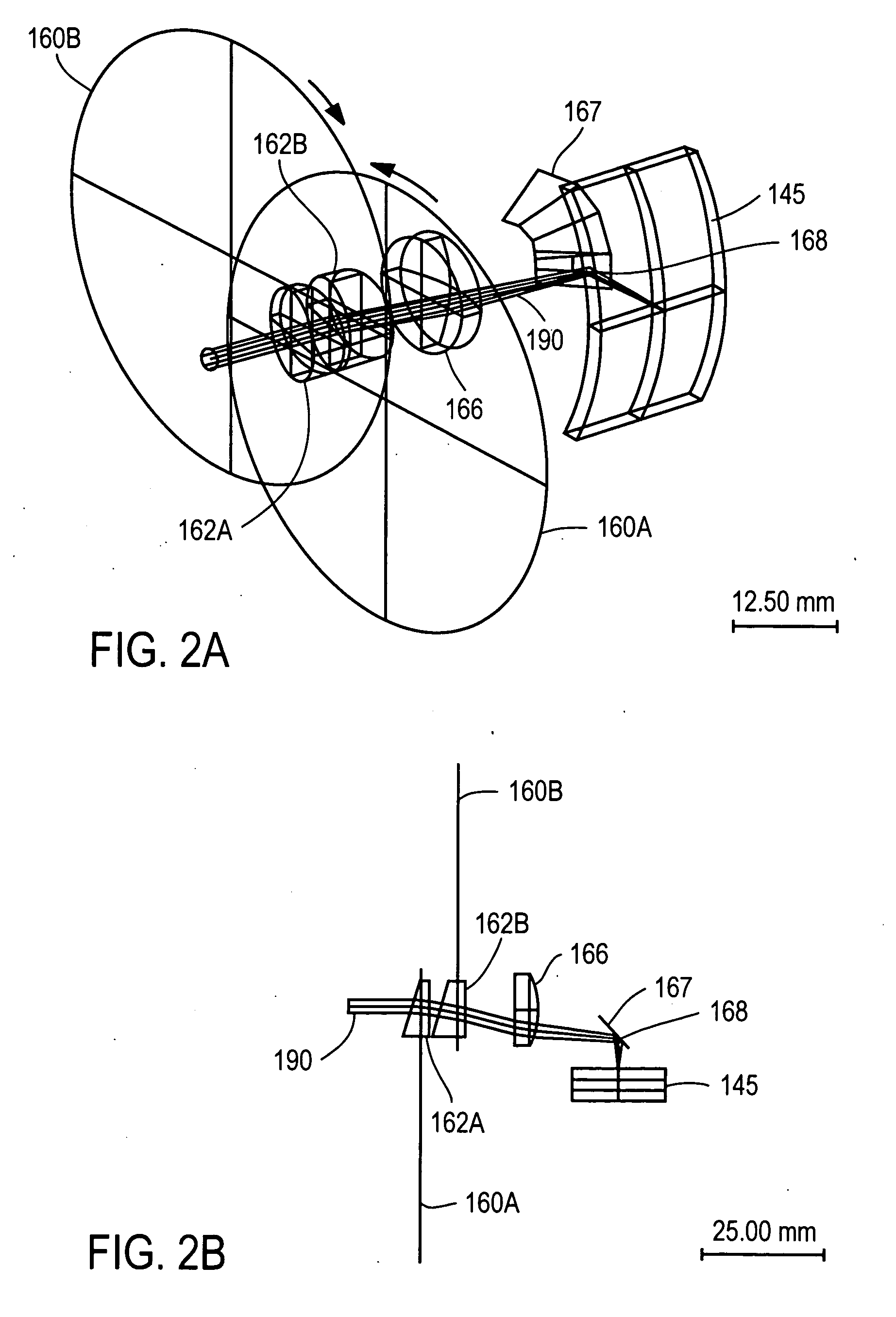
[0031] The system 100 operates as follows. The optical source 110, for example a pulsed laser, generates an optical beam that is delivered to the handpiece 130 via the fiber 120. The optical beam enters the handpiece at input port 150 and is collimated by optics 152 (e.g., a collimating lens). The counter-rotating disks 160 shown in FIGS. 2A-2C each include many facets 162 a...


PUM


Abstract

An optical beam is delivered to internal target tissue, for example via two counter-rotating disks or via a single rotatable component. In one approach, two counter-rotating disks deflect an incident optical beam in a manner that generates an irradiation pattern at the target tissue. In another approach, a rotatable component includes a plurality of deflection sectors arranged around a rotation axis, and each sector deflects an incident optical beam as the sector rotates through the beam to generate an irradiation pattern at the target tissue. A probe maintains an optical channel within the human body so that the deflected optical beam can be delivered to the target tissue.

Description

CROSS-REFERENCE TO RELATED APPLICATION(S) [0001] This application (a) claims priority under 35 U.S.C. § 119(e) to U.S. Provisional Patent Application Ser. No. 60 / 677,682, “Optically-Induced Treatment of Internal Tissue,” filed May 3, 2005; (b) claims priority to U.S. Provisional Patent Application Ser. No. 60 / 652,891, “High Efficiency, High Speed Optical Pattern Generator Using a Single Rotating Component,” filed Feb. 14, 2005; and (c) is a continuation-in-part of U.S. patent application Ser. No. 11 / 158,907, “Optical Pattern Generator Using a Single Rotating Component,” filed Jun. 20, 2005, which is a continuation-in-part of U.S. patent application Ser. No. 10 / 750,790, “High Speed, High Efficiency Optical Pattern Generator using Rotating Optical Elements,” filed Dec. 31, 2003, and which also claims priority to U.S. Provisional Patent Application Ser. No. 60 / 652,891, “High Efficiency, High Speed Optical Pattern Generator Using a Single Rotating Component,” filed Feb. 14, 2005. The su...

Claims


Application Information

Patent Timeline
Patent Type & Authority Applications(United States)
IPC IPC(8): A61B18/18
CPCA61B18/201A61B2018/2272G02B5/09G02B26/108G02B26/12
Inventor DEBENEDICTIS, LEONARD C.BROOME, BARRY G.FRANGINEAS, GEORGE
Owner RELIANT TECH INC
Why Eureka
Try Eureka