
System, method and apparatus for self-cleaning dry etch

a technology of dry etching and process chamber, which is applied in the direction of cleaning hollow objects, liquid cleaning, coatings, etc., can solve the problems of affecting the operation of the plasma, affecting the cleaning effect of the process chamber, so as to reduce the cleaning requirement of the process chamber

Active Publication Date: 2006-10-05
LAM RES CORP
View PDF12 Cites 5 Cited by
  • Summary
  • Abstract
  • Description
  • Claims
  • Application Information

AI Technical Summary

Benefits of technology

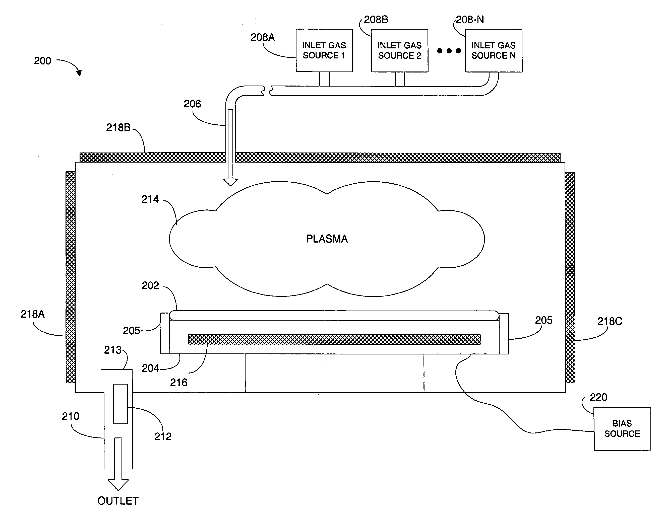
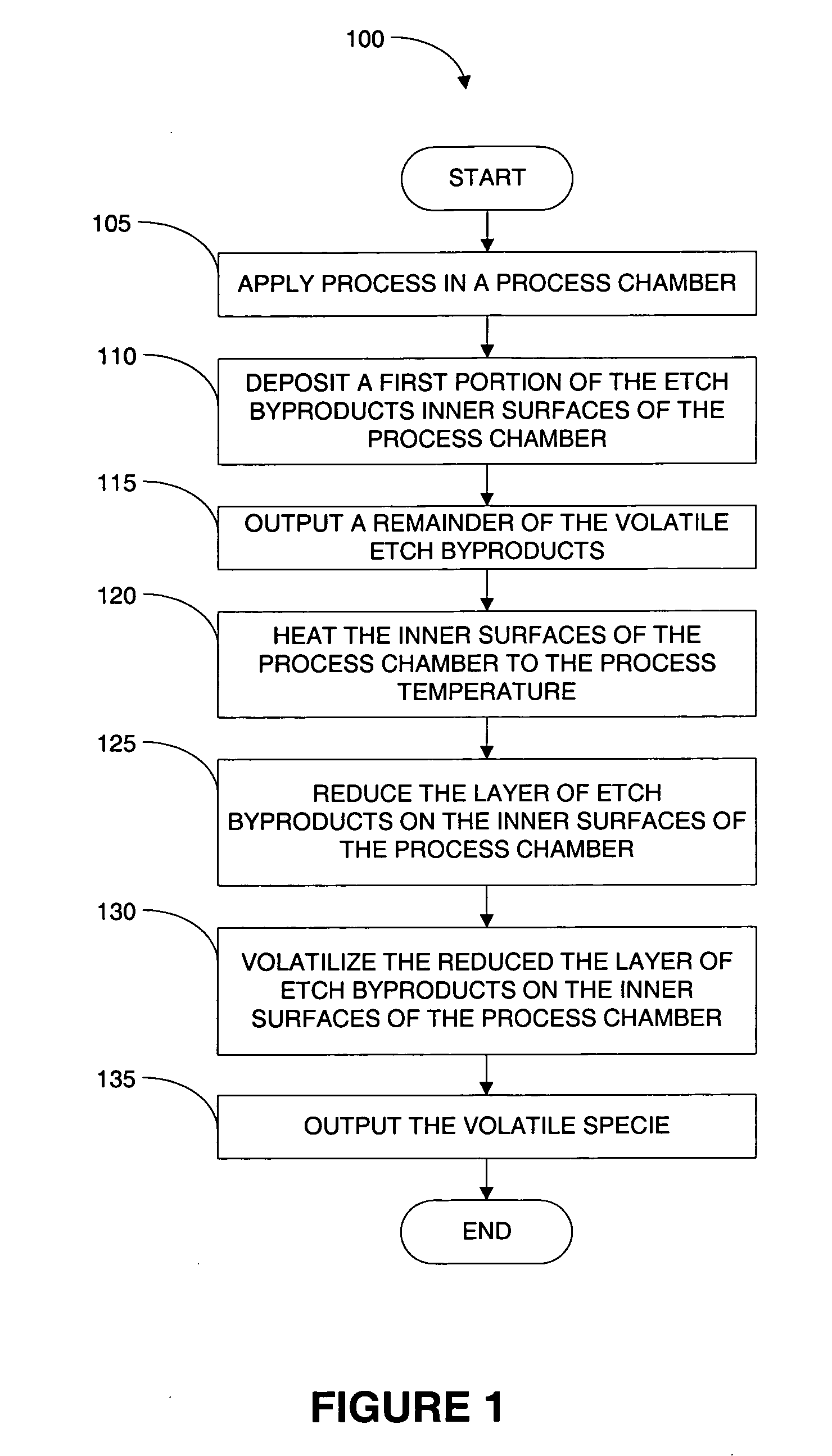
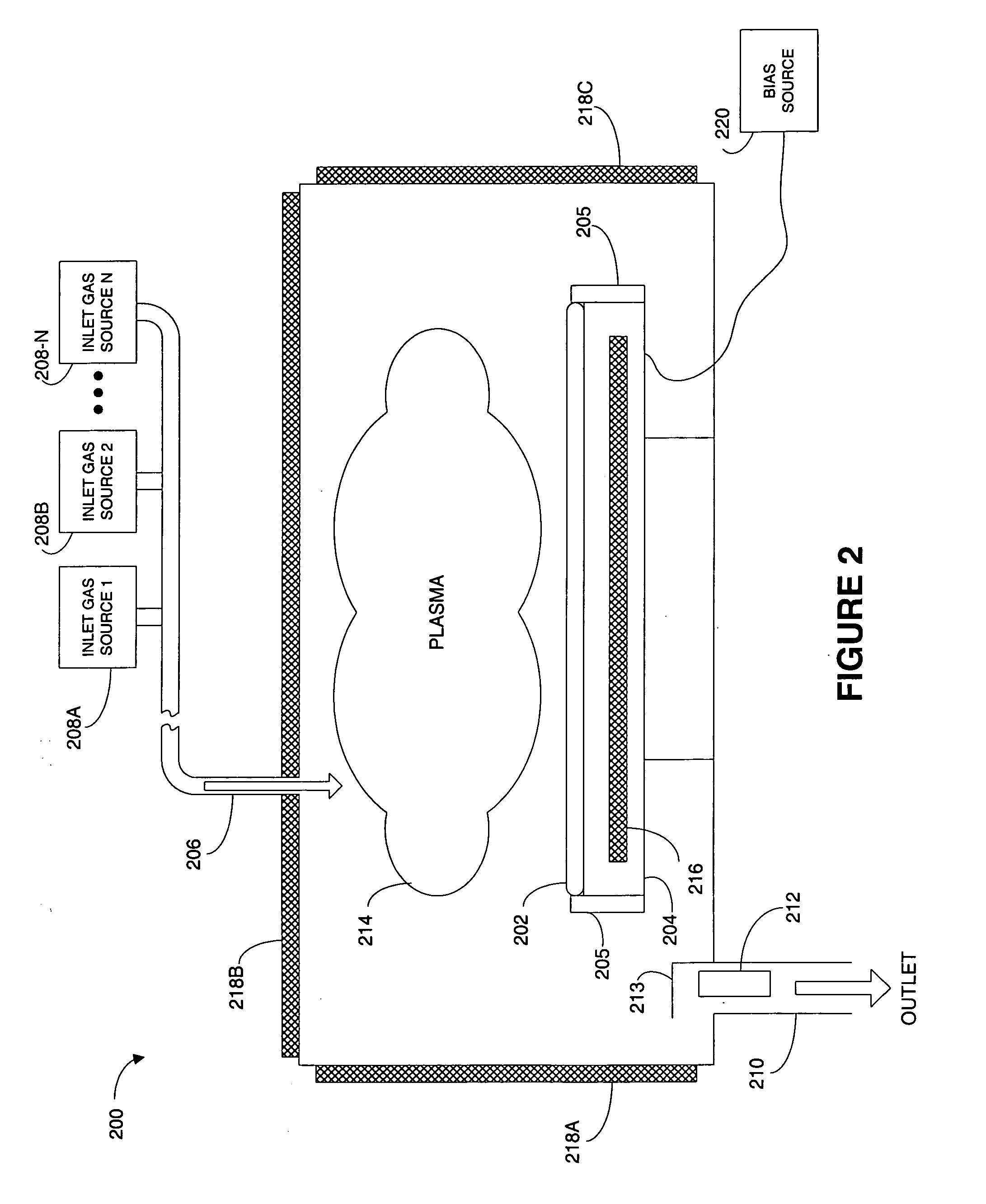
The present invention provides a system and method for reducing the process chamber cleaning requirement in a semiconductor device manufacturing process. This is achieved by using a cleaning chemistry that is reactive with a second species deposited on the inner surface of the processing chamber, converting it to a volatile species that can be easily removed. The cleaning chemistry can also include a heat source to heat the processing chamber and substrate, and a bias source to control the voltage. The method can also include etching the substrate surface while simultaneously outputting a volatile species and depositing a non-volatile species on the inner surfaces of the processing chamber. The non-volatile species can be converted to the volatile species through a chemical reaction with the cleaning chemistry. The invention provides a more efficient and effective way to clean the processing chamber, reducing the time and cost associated with the process.

Problems solved by technology

The particles can contaminate the substrates being etched in the chamber.
The conductive byproduct deposits can also interfere with the operation of the plasma.
Due to this exposure, these parts ultimately erode or accumulate byproduct buildup, requiring replacement or thorough cleaning.
However, the cleaning and / or replacement costs of these lining parts can become very expensive both in actual cost and in lost production time required for the cleaning and replacement.
The frequent cleaning requirement reduces the time the process chamber can available for etching processes and thereby reduces the substrate throughput of the process chamber.

Method used


Image

  • System, method and apparatus for self-cleaning dry etch
  • System, method and apparatus for self-cleaning dry etch
  • System, method and apparatus for self-cleaning dry etch

Examples


Embodiment Construction

[0034] Several exemplary embodiments for an improved chamber cleaning process will now be described. It will be apparent to those skilled in the art that the present invention may be practiced without some or all of the specific details set forth herein.

[0035] Halogen gas (e.g., Chlorine, Fluorine, Bromine, etc.) based processes can be used to dry etch copper for interconnect applications. Halogen dry etch processes can be performed for copper etch back for stress free polish or planarization of damascene copper or patterning of copper interconnects such as described in U.S. patent application Ser. No. 10 / 390,117 filed on Mar. 14, 2003, entitled “System, Method and Apparatus For Improved Global Dual-Damascene Planarization,” which is incorporated herein by reference in its entirety. And is also described in U.S. patent application Ser. No. 10 / 390,520 filed on Mar. 14, 2003, entitled “System, Method and Apparatus For Improved Local Dual-Damascene Planarization,” which is also incorp...


PUM

PropertyMeasurementUnit
temperatureaaaaaaaaaa
heataaaaaaaaaa
timeaaaaaaaaaa

Abstract

A method for cleaning a processing chamber that includes heating an inner surface of the processing chamber to a first temperature. The first temperature can be sufficient to cause a first species to become volatile. The first species can be one of several species deposited on the inner surface. A cleaning chemistry is injected into the processing chamber. The cleaning chemistry can be reactive with a second one of the species to convert the second species to the first species. The volatilized first species can also be output from the processing chamber. A system for cleaning the process chamber is also described.

Description

CROSS REFERENCE TO RELATED APPLICATIONS [0001] This application is a divisional application of and claims priority from U.S. patent application Ser. No. 10 / 802,460, filed Mar. 16, 2004 and entitled “System, Method and Apparatus for Self-Cleaning Dry Etch” which is incorporated herein by reference in its entirety for all purposes. U.S. patent application Ser. No. 10 / 802,460 is a continuation-in-part of and claims priority from U.S. patent application Ser. No. 10 / 390,117 filed on Mar. 14, 2003 and entitled “System, Method and Apparatus For Improved Global Dual-Damascene Planarization,” which is incorporated herein by reference in its entirety. U.S. patent application Ser. No. 10 / 802,460 is also a continuation-in-part of and claims priority from U.S. patent application Ser. No. 10 / 390,520 filed on Mar. 14, 2003 and entitled “System, Method and Apparatus For Improved Local Dual-Damascene Planarization,” which is incorporated herein by reference in its entirety. U.S. patent application S...

Claims


Application Information

Patent Timeline
Patent Type & Authority Applications(United States)
IPC IPC(8): B08B9/00H01J37/32H01L21/00H01L21/302H01L21/3065H01L21/321H01L21/3213H01L21/44H01L21/461H01L21/4763H01L21/768H01L23/48H01L23/52H01L29/24H01L29/40H01L33/00
CPCB08B7/00Y10S438/905B08B7/0071H01J37/3244H01J37/32522H01J37/32862H01J2237/022H01L21/3065H01L21/32115H01L21/32136H01L21/67034H01L21/67051H01L21/67069H01L21/6708H01L21/7684B08B7/0035B08B9/00B44C1/22H01L21/302
Inventor BAILEY, ANDREW D. IIILOHOKARE, SHRIKANT P.HOWALD, ARTHUR M.KIM, YUNSANG
Owner LAM RES CORP
Learn More