

Time of flight mass spectrometer
a mass spectrometer and time-of-flight technology, applied in the field of time-of-flight mass spectrometer, can solve the problems of difficult to incorporate a long straight path in a tof-ms, tof-mss using any type of loop orbit, and problems, etc., to achieve the effect of improving the accuracy of mass analysis and high reliability
- Summary
- Abstract
- Description
- Claims
- Application Information
AI Technical Summary
Benefits of technology
Problems solved by technology
Method used
Image

Examples
embodiment 1
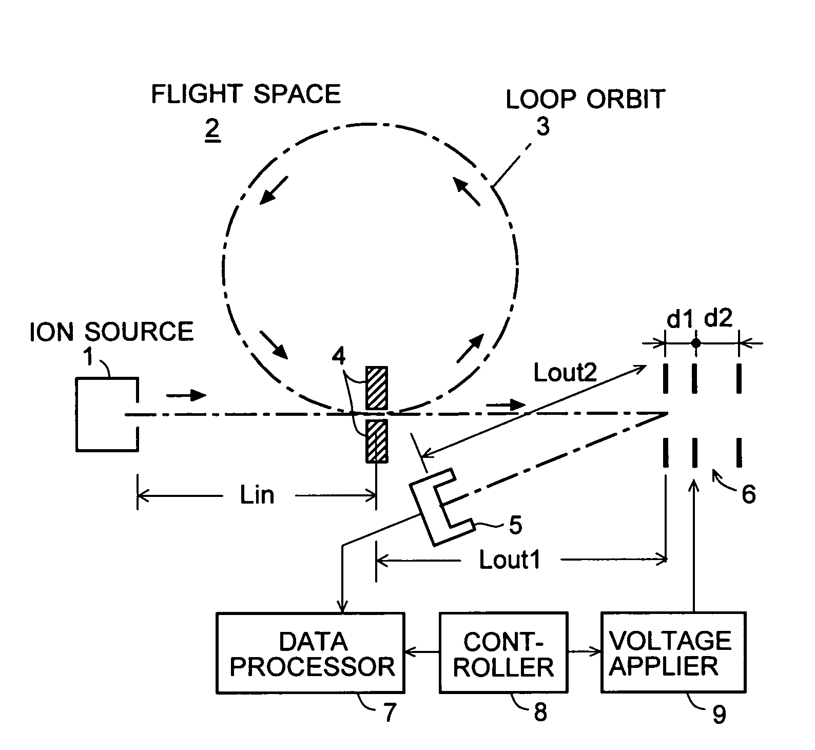
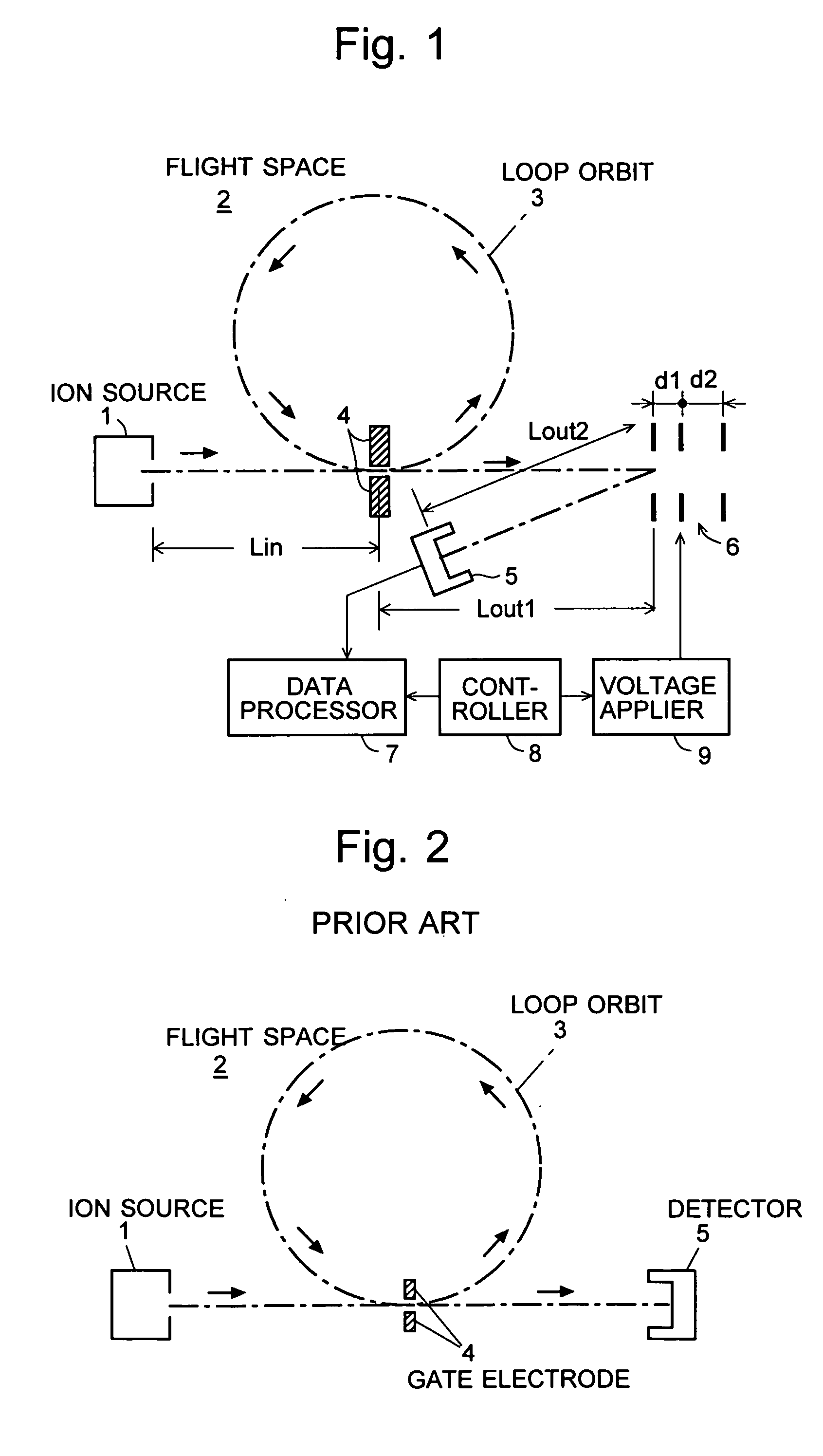
[0032] An embodiment (Embodiment 1) of the time of flight mass spectrometer according to the present invention is described with reference to the attached drawings. FIG. 1 is a schematic diagram of the TOFMS of the present embodiment. It should be noted that those components which are identical or corresponding to some components shown in FIG. 2 are denoted by the same numerals.
[0033] In FIG. 1, various kinds of ions extracted from the ion source 1 are injected through the gate electrode 4 into the loop orbit 3 in the flight space 2. Then, after flying in the loop orbit 3 once or multiple times, the ions leave the loop orbit 3 and are ejected from the flight space 2 immediately after they pass through the gate electrode 4. Outside the exit of the flight space 2, a reflector 6 consisting of reflecting electrodes is located for generating an electric field, which repels the ions toward the detector 5. Under the command of the controller 8, the voltage applier 9 varies the voltage app...
embodiment 2
[0060] Another embodiment (Embodiment 2) of the time of flight mass spectrometer according to the present invention is hereby described. The difference between Embodiment 1 and Embodiment 2 exists in the steps of the analysis carried out by the TOFMS. The following description explains this difference, referring to the flow chart shown in FIG. 8.
[0061] First, as described previously, the voltage V1 applied to the first stage of the reflector 6 is set at a predetermined level (e.g. 2100 [V]), and the first round of the measurement is carried out to collect a first set of flight time data (Step S11). Next, the voltage V1 applied to the first stage of the reflector 6 is changed to a new level (e.g. 2050 [V]), and the second round of the measurement is carried out to collect a second set of flight time data (Step S12). Subsequently, the voltage V1 applied to the first stage of the reflector 6 is again changed to a new level (e.g. 2000 [V]), and the third round of the measurement is car...
PUM
 Abstract
Description
Claims
Application Information