RFID tag reader/writer

a technology of rfid tags and readers, applied in the direction of instruments, near-field systems using receivers, burglar alarm mechanical actuation, etc., can solve the problems of limiting the utility of rfid tags, the solution still has the risk of failure to ensure normal radio communication, and the drawback of reading the information from each selected rfid tag is similar, so as to reduce the leakage of communication signals into the exterior of the reader/writer, the effect of smooth feeding

Active Publication Date: 2006-10-05
BROTHER KOGYO KK
View PDF20 Cites 65 Cited by
  • Summary
  • Abstract
  • Description
  • Claims
  • Application Information

AI Technical Summary

Benefits of technology

[0061] In another preferred arrangement of the eighth aspect of the invention, the RFID tag reader/writer has an outlet through which the RFID tag circuit element is fed out of the RFID tag reader/writer after the RFID tag information of the IC circuit portion has been accessed in the accessible area. In this arrangement, the RFID tag circuit element the IC circuit portion of which has been accessed to read or write the RFID tag information in the accessible area can be smoothly fed out of the RFID tag reader/writer.
[0062] In another preferred arrangement of the eighth aspect of the invention, the above-described outlet is spaced from the directional antenna in a direction substantially perpendicular to the direction of directivity. In this arrangement, the intensity of the communication signal received at the outlet from the directional antenna is relatively low, since the outlet is spaced from the directional antenna in the direction substantially perpendicular to the direction of directivity, so that the leakage of the communication signal into the exterior of the reader/writer can be reduced.
[0063] In another preferred arrangement of the eighth aspect of the invention, the above-described outlet is positioned such that the outlet is spaced from the directional antenna in a direction in which an electric field intensity of the directional antenna is lower by at least 10 dB than that in the direction of directivity of the directional antenna. In this arrangement wherein the electric field intensity at the outlet is lower by at least 10 dB than that at a position spaced from the directional antenna in the direction of directivity, the leakage of the communication signal ...

Problems solved by technology

However, the use of these frequency bands suffers from a short distance of the radio communication, and unfavorably limits the utility of the RFID tags.
There exists a similar drawback for reading the information from each selected RFID ta...

Method used


Image

  • RFID tag reader/writer
  • RFID tag reader/writer
  • RFID tag reader/writer

Examples


embodiment 1

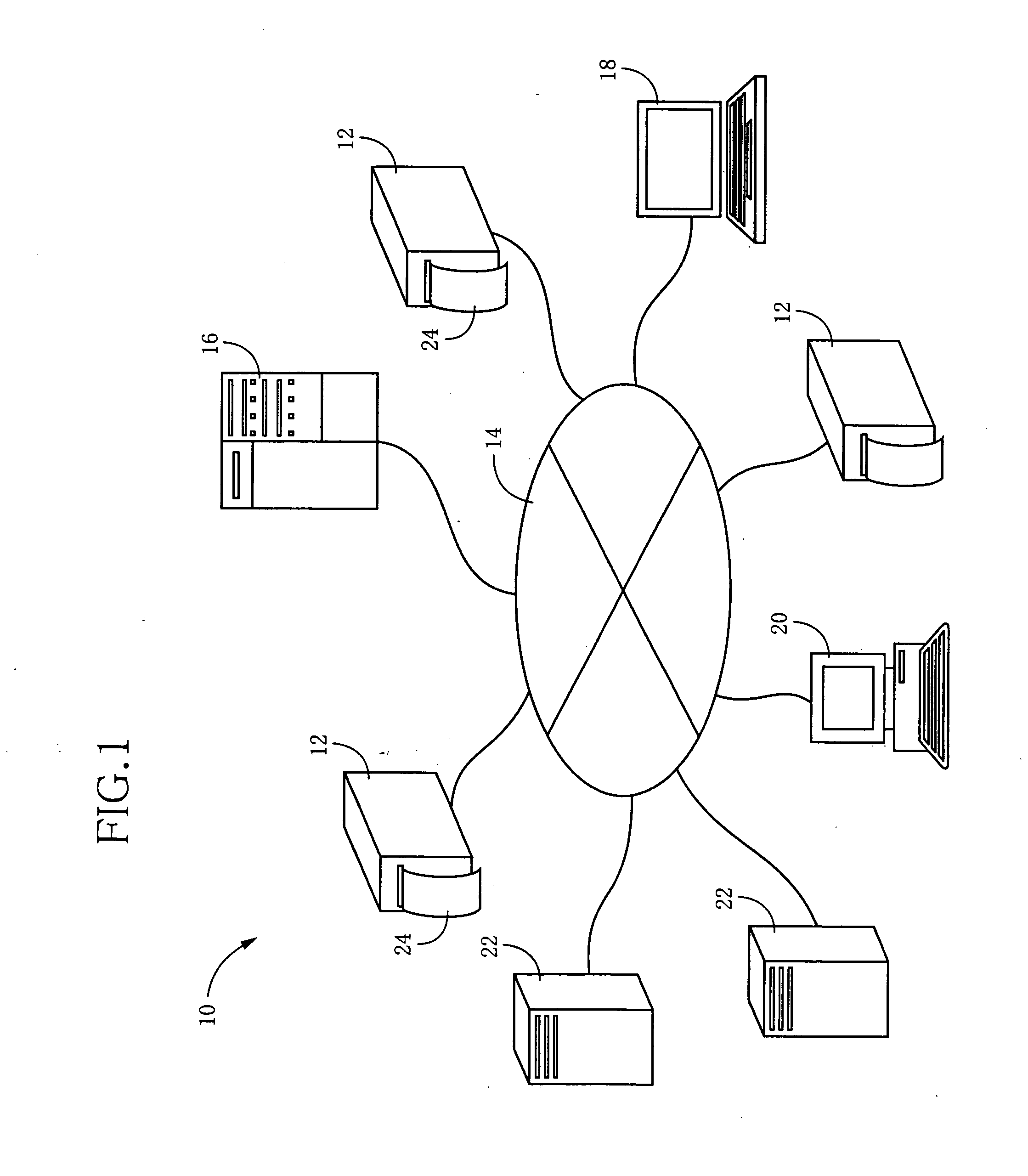
[0127] Referring to FIG. 1, there is illustrated an RFID system 10 to which the first through eighth aspects of this invention are suitably applicable. In this REID system 10, a plurality of RFID tag reader / writer devices 12 each constructed according to one embodiment of the present invention are connected to a route server 16, a terminal 18, a general-purpose computer 20, and a plurality of information servers 22, through a wire (cable) or wireless communication line 14. Each RFID tag reader / writer 12 is an RFID tag information communicating device arranged to effect at least one of an operation to write desired information on an RFID tag selected for communication therewith, and an operation to read desired information from the selected RFID tag.

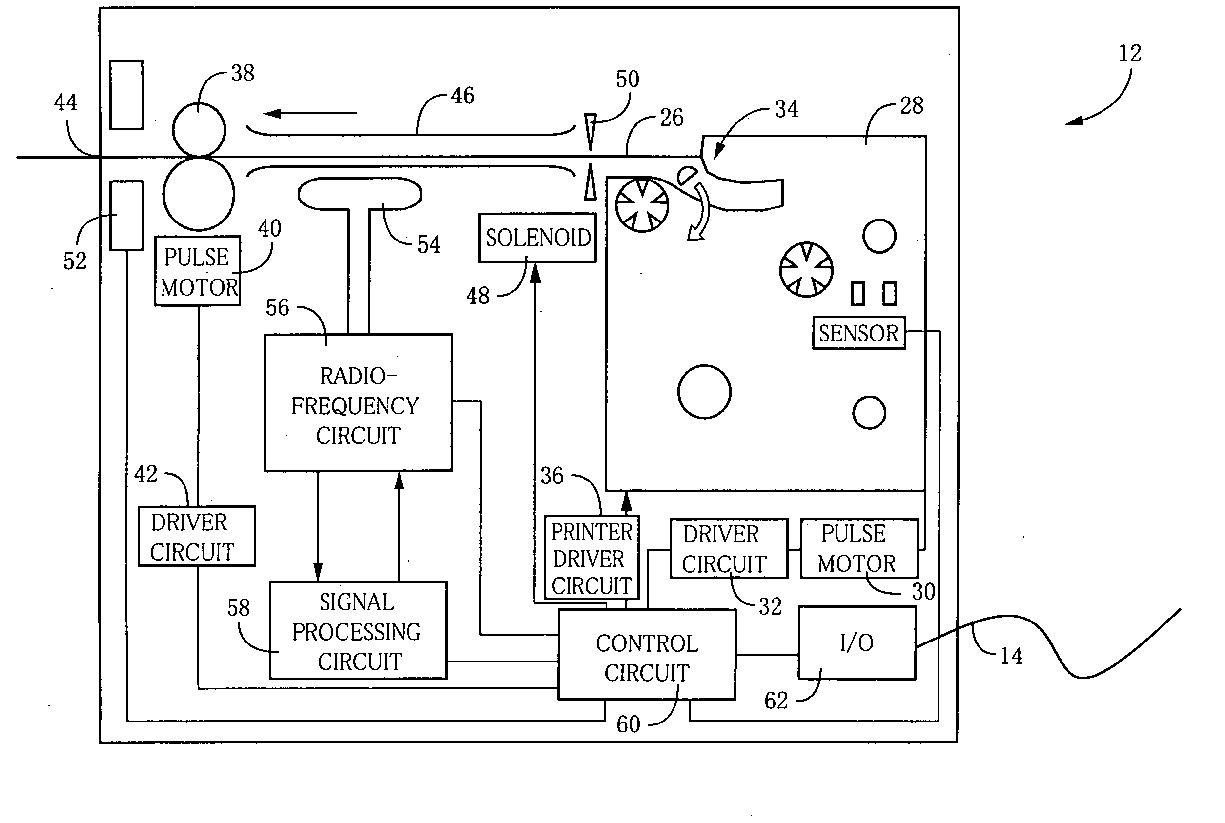
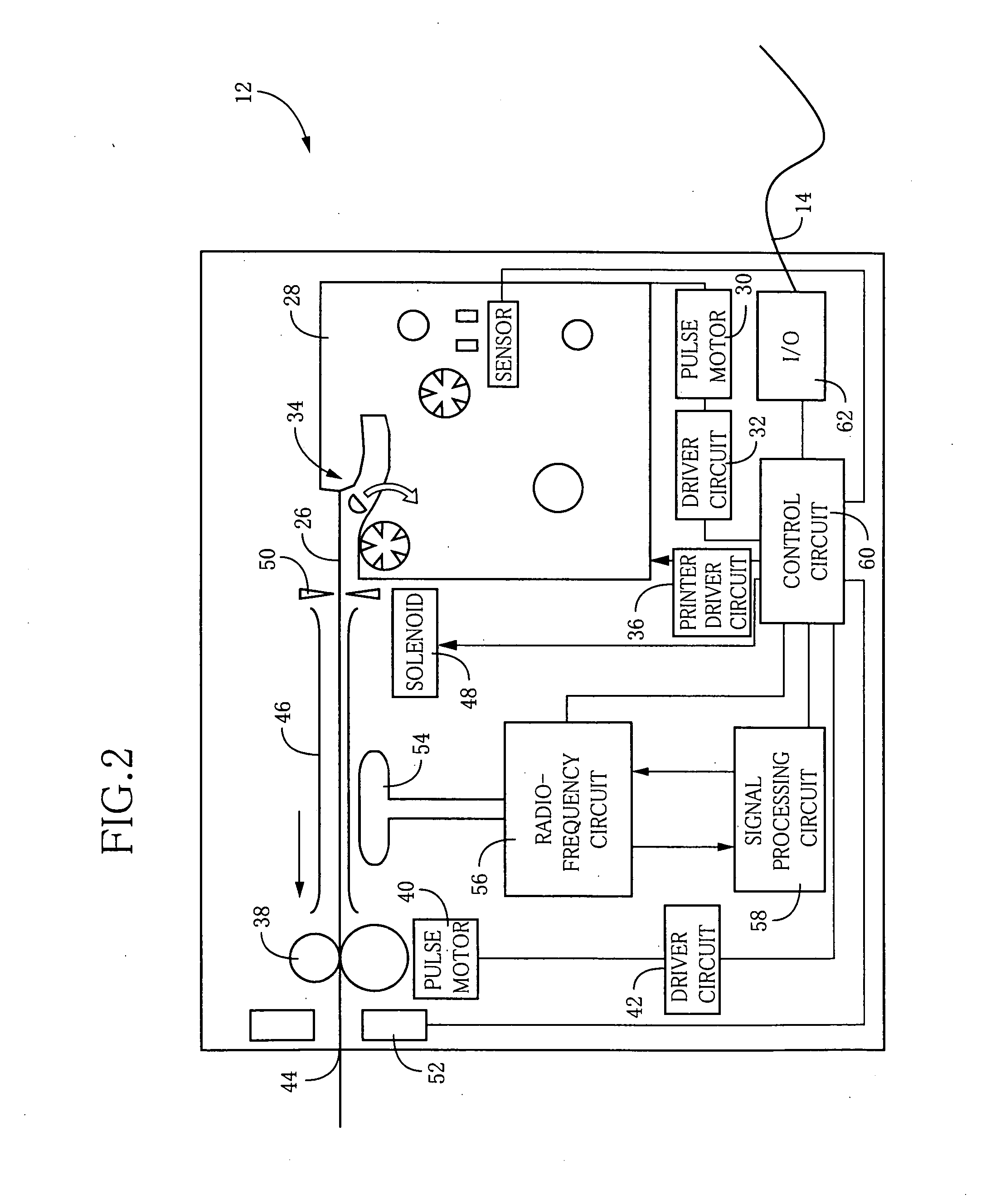
[0128] Referring to FIG. 2, there is illustrated an arrangement of the above-described RFID tag reader / writer 12. This RFID tag reader / writer 12 is arranged to produce RFID tags 24 shown in FIG. 4, in an instant, so as to meet a need of ...

embodiment 2

[0175] Referring to FIG. 36, there is schematically shown in detail an arrangement of an RFID tag reader 202 according to the present embodiment. This RFID tag reader 202 is suitably used in a communication system such as the communication system 10 in the first embodiment described above. The portions of the present embodiment which are identical with those of the first embodiment will not be described.

[0176] As shown in FIG. 36, the RFID tag reader 202 includes a removably installed cartridge (RFID tag circuit-element accommodating portion) 220 which accommodates a plurality of RFID tag circuit elements 210A such that the circuit elements 210A can be sequentially taken out. Since each RFID tag circuit element 210A in the present embodiment is identical in construction with the RFID tag circuit element 24a in the first embodiment described above, the description of the RFID tag circuit element 210A is omitted.

[0177]FIG. 37 is a view taken in a direction of arrow-headed line III o...

embodiment 3

[0213] Referring to FIG. 44, there will be described a third embodiment of this invention.

[0214] The present embodiment utilizes a difference between planes of polarization of the device-side and tag-side antennas. The same reference signs as used in the preceding second embodiment will be used to identify the corresponding elements of the third embodiment, the description of which will be omitted where appropriate.

[0215]FIG. 44 is a view which schematically shows in detail an arrangement of an RFID tag reader 202′ according to the present embodiment and which corresponds to that of FIG. 36. In the interest of brevity, the feeding guides 283 and the sensor 286 are not shown in FIG. 44.

[0216] As is apparent from FIG. 44, the present embodiment is different from the second embodiment in the positional relationship between the cartridge 220 and the device-side antenna 240, and in the direction in which the tag tape 228 taken out from the cartridge is fed.

[0217] In the RFID tag read...


PUM


Abstract

An RFID tag reader/writer having a high degree of stability of communication with only a desired RFID tag. The frequency of a carrier wave to be transmitted from the RFID tag reader/writer is set on the basis of a resonance frequency of an antenna of the RFID tag located within a predetermined nearby communication area, which resonance frequency changes due to mutual coupling between the antenna of the RFID tag and an antenna of the RFID tag reader/writer. According to this setting, the RFID tag located within the nearby communication area has a high degree of sensitivity, and the RFID tag located outside the nearby communication area has a low degree of sensitivity, so that it is possible to effectively prevent an interference between the communication of the RFID tag reader/writer with the selected RFID tag and the communication of the reader/writer with the other or non-selected RFID tag.

Description

[0001] The present application is a Continuation0in-Part of International Application No. PCT / JP2004 / 011847 filed Aug. 18, 2004, which claims the benefits of Japanese Patent Application No. 2003-327687 filed Sep. 19, 2003, Japanese Patent Application No. 2003-359545 filed Oct. 20, 2003, Japanese Patent Application No. 2004-027768 filed Feb. 4, 2004, and Japanese Patent Application No. 2004-027769 filed Feb. 4, 2004. BACKGROUND OF THE INVENTION [0002] 1. Field of the Invention [0003] The present invention relates to a radio or wireless tag reader / writer operable to read information from and write information on a radio or wireless tag which is capable of information writing and reading by radio or wireless communication. [0004] 2. Description of the Related Art [0005] There is known an RFID (Radio Frequency Identification) system wherein an RFID tag reader / writer or a read-only interrogator is operable in a non-contact fashion to write information on and read information from small-s...

Claims


Application Information

Patent Timeline
IPC IPC(8): G08B13/14G06K7/00G06K19/07H04B5/02
CPCB41J3/50G06K7/0008G06K7/10069H04B5/02G06K19/0723H04B5/0056H04B5/0062G06K17/0025
Inventor NAGAI, TAKUYATAKI, KAZUNARIOHASHI, TSUYOSHI
Owner BROTHER KOGYO KK
Why Eureka
Try Eureka